

Sauna & Steam
Oceanic Saunas 01902 450 550 sales@oceanic-saunas.co.uk
9
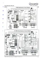
Steam Generator Manual
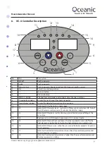
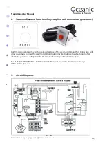
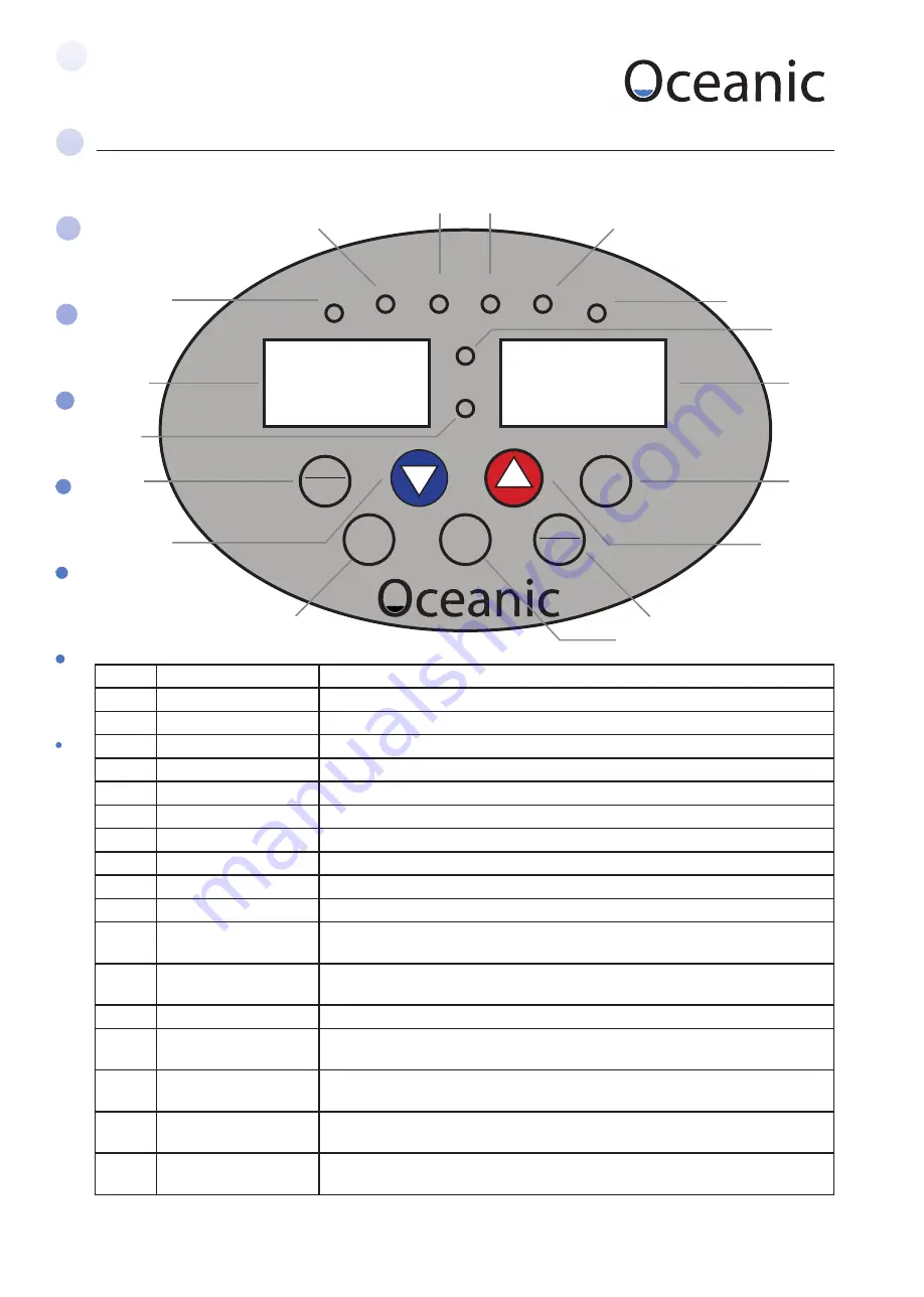
6. OC-A Controller Description
No
Part
Description
1
On/off
Push to operate
2
Light
Push to operate
3
Drain Control
Push to operate / Keep pressed for SOD/ Keep pressed for normal
4
Set
Preset time and temperature
5
/\
Increase button
6
\/
Decrease button
7
/ ºC/F / ENTER
Change from centigrade to Fahrenheit / Enter change in settings
8
Time display window
Display the work time of the steam generator
9
Temp display window
Display the detected temperature of steam room
10
L1
Indicator LED for the light in steam room
11
L2
Indicator LED for water level – red, water is filling - green water level OK. Note if
the LED remains red in excess of 5 minutes check water supply.
12
L3
Indicator LED for drain - red for draining - green for draining and filling at the
same time
13
L4
Red means it is in SOD mode. Green means it is in normal mode
14
L5
Indicator LED for over heat, red means the steam generator was cut off as the
heat element is too hot (lack of water, the heat elements may worked in air)
15
L6
Indicator LED for pressure - when the pressure in the boiler exceeds 1.2kg/c m2.
It will switch on.
16
L7
Indicates the detected temperature is lower than the preset temperature and
steam generator is heating.
17
L8
Indicates the detected temperature is higher than the preset temperature and
the steam generator is idling.
L1
L2
L3
L4
L5
L6
L7
L8
C/F
ENTER
DRAIN
LIGHT
SET
1
2
3
4
7
5
6
17
8
9
16
15
14
13
12
11
10
ON
OFF


