19
OCL OPERATING MANUAL
© 2002 Design, 2014
Doc. No. 12-5378-r01 (4/9/15)
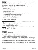
> MODs (Max Operating Depths) will not be displayed on the FO2 set screen.
> internally, it will keep track of O2 data for use if FO2 is subsequently set for Nitrox for repetitive dives.
When FO2 is set for Nitrox -
> The Air option will not be displayed as an FO2 setting until 24 hours elapse after the last dive.
When FO2 is set for OFF (Gas 2 only) -
> The Gas Switch routine will not be available during dives.
FO2 50% Default -
> When set OFF, FO2 values will remain set at their last settings saved until 24 hours elapse without conducting a dive.
> When set ON and FO2 is set for Nitrox, 10 minutes on the surface after that dive the FO2 will be displayed as 50
and further dives will be calculated based on 50% O2 for oxygen calculations and 21% O2 for Nitrogen calculations
(79% Nitrogen), unless FO2 is set before the dive.
> FO2 will continue to reset to the Default after repetitive dives until 24 hours elapse with no dive, or the Default is set
OFF.
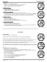
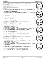
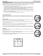
Set Gas Lead-in,
information includes (Fig. 36):
> Graphics SEt and GAS
• A (< 2 sec) - to step forward to Set A Lead-in.
• M (< 2 sec) - to step back to Log Lead-in.
• S (< 2 sec) - to access Set FO2 Gas 1.
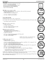
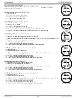
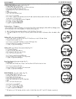
Set Gas 1,
information includes (Fig. 37A, B, C):
> Graphic SEt if Air; or Max Depth allowed for the PO2 alarm set with FT (or M) icon if Nitrox
> Gas 1 icon
> PO2 alarm value set (ATA) with PO2 icon if Nitrox, blank if Air
> Graphic Air, or numeric FO2 value if Nitrox, flashing, with FO2 icon
• A (press/hold), while the FO2 Set Point digits are flashing - to scroll upward through the Set Points from Air to
21 through 100 in 1% increments, at a rate of 8 per second.
The scroll will stop when the button is released, or
momentarily at 32, then at 50, the at 80 %.
• A (< 2 sec) - to step upward through FO2 Set Points.
• M (< 2 sec) - to step back through FO2 Set Points.
• S (< 2 sec) - save the FO2 setting and flash the PO2 digits if Nitrox (a numerical value), or access Set Gas 2 if Air.
• S (2 sec) - to step back to the Set Gas Lead-in screen without changing the Gas 1 FO2 setting.
• A (< 2 sec) - to step upward through PO2 Alarm Set Points from 1.00 to 1.60 (ATA) in .05 increments.
• M (< 2 sec) - to step back through PO2 Set Points.
• S (< 2 sec) - to save the PO2 setting and access Set Gas 2.
• S (2 sec) - to step back to the FO2 digits flashing without changing the PO2 Alarm setting.
• M (2 sec), or if no button is pressed during a 2 minute period - to revert to the Surface Main.
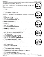
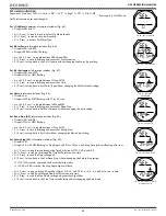
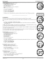
Set Gas 2,
information includes (Fig. 38A, B):
> Graphic SEt if OFF or Air; or Max Depth allowed for the PO2 alarm set with FT (or M) icon if Nitrox
> Gas 2 icon
> PO2 alarm value set (ATA) with PO2 icon if Nitrox, blank if Air
> Graphic OFF or Air, or numeric FO2 value if Nitrox, flashing, with FO2 icon
• A (press/hold), while the FO2 Set Point digits are flashing - to scroll upward through the Set Points from OFF to Air
to 21 through 100 in 1% increments, at a rate of 8 per second.
The scroll will stop when the button is released, or
momentarily at 32, then at 50, then at 80 %.
• A (< 2 sec) - to step upward through FO2 Set Points.
• M (< 2 sec) - to step back through FO2 Set Points.
• S (< 2 sec) - save the FO2 setting and flash the PO2 digits if Nitrox (a numerical value), or revert to the Set Gas Lead-
in screen if OFF or Air.
• S (2 sec) - to step back to the Set Gas 1 screen without changing the Gas 2 FO2 setting.
• A (< 2 sec) - to step upward through PO2 Alarm Set Points from 1.00 to 1.60 (ATA) in .05 increments.
• M (< 2 sec) - to step back through PO2 Set Points.
• S (< 2 sec) - to save the PO2 setting and access Set Gas 2.
• S (2 sec) - to step back to the FO2 digits flashing without changing the PO2 Alarm setting.
• M (2 sec), or if no button is pressed during a 2 minute period - to revert to the Surface Main.
Fig. 37B - SET GAS 1
(FO2 for Nitrox)
Fig. 36 - SET G LEAD-IN
Fig. 38A - SET GAS 2
Fig. 38B - SET GAS 2
(FO2, then PO2 Alarm)
Fig. 37A - SET GAS 1
(FO2 for Air)
Fig. 37C - SET GAS 1
(PO2 Alarm)
Summary of Contents for OCL
Page 15: ...15 OCL OPERATING MANUAL 2002 Design 2014 Doc No 12 5378 r01 4 9 15 NORM SURFACE MODES...
Page 24: ...24 OCL OPERATING MANUAL 2002 Design 2014 Doc No 12 5378 r01 4 9 15 DIVE MODE FEATURES...
Page 27: ...27 OCL OPERATING MANUAL 2002 Design 2014 Doc No 12 5378 r01 4 9 15 NORM DIVE MODE...
Page 34: ...34 OCL OPERATING MANUAL 2002 Design 2014 Doc No 12 5378 r01 4 9 15 DIGITAL GAUGE MODE...
Page 37: ...37 OCL OPERATING MANUAL 2002 Design 2014 Doc No 12 5378 r01 4 9 15 FREE DIVE MODE...
Page 42: ...42 OCL OPERATING MANUAL 2002 Design 2014 Doc No 12 5378 r01 4 9 15 REFERENCE...
Page 47: ...47 OCL OPERATING MANUAL 2002 Design 2014 Doc No 12 5378 r01 4 9 15 TECHNICAL DATA...

