29
VT 4.0 OPERATING MANUAL
© 2002 Design, 2011
Doc. No. 12-5213-r02 (9/6/11)
VIOLATION GAUGE MODE (VGM)
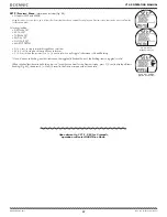
If a Deco Stop Depth greater than 70 FT (21 M) is required, operation will enter VGM. This would be preceded by DV2.
Operation would then continue in VGM during the remainder of that dive and for 24 hours after surfacing.
VGM turns the VT 4.0 into a digital instrument without any decompression or oxygen related calculations or displays.
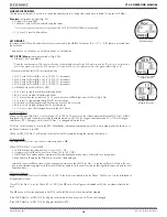
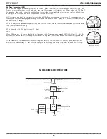
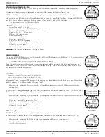
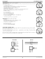
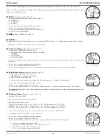
Upon activation of VGM, the Audible will sound during which the alarm LED and full TLBG* will flash. The graphic VIOLATION
and (2) Up Arrows will also be displayed flashing, in place of Deco data (Fig. 60), until on the surface.
*After the audible is silenced, the TLBG will be removed.
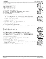
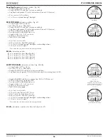
VGM Main,
information includes (Fig. 61) -
> Current Depth with FT (or M) icon.
> (2) Up Arrows with graphic VIOLATION, flashing until on surface.
> Pressure with PSI (or BAR) and Link icons.
> Graphic GAS1 (or 2, 3, 4), one in use.
> ATR (up to 199 min) with icons.
> VARI while ascending.
• A (< 2 sec) to access ALTs.
• M (2 sec) to access TMT Switching*.
• S (< 2 sec) to activate Backlight or acknowledge alarms.
• S (2 sec) to access Compass*.
*These items can only be accessed while viewing the Main.
VGM ALTs,
information is similar to Deco ALTs (Fig. 53 & 54).
VGM ON SURFACE
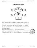
The graphic VIOLATION flashes for the first 10 minutes (Fig. 62), then VIOL alternates with NORM (each On 3 seconds) until unit
shut down after 24 hours with no dives*.
*A full 24 hour surface interval must then be served before all functions are restored.
During that 24 hours, access to all menus and screens is available except those associated with Ni-O2 calculations such as
Desat, Plan, Set FO2. The Fly countdown timer provides the time remaining (of the 24 hours required) before normal operation
can resume with full features and functions.
HIGH PO2
Warning >> at Alarm Set Point value minus 0.20 (1.00 to 1.40).
Alarm >> at Set Point value, except in Deco then at 1.60 only.
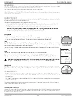
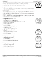
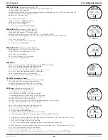
When partial pressure of oxygen (PO2) increases to the Warning level; the Audible will sound during which an Up Arrow and
the PO2 value with icon will flash in place of Pressure (Fig. 63).
> After the Audible is silenced, Pressure is restored, and the Up Arrow remains on solid until PO2 decreases below the
warning level.
If PO2 continues to increase and reaches the PO2 Alarm level, the Audible will sound again during which (2) Up Arrows and the
PO2 value with icon will flash in place of Pressure (Fig. 64).
> After the Audible is silenced, Pressure is restored, and the Up Arrows remain on solid until PO2 decreases below the alarm
level, at which time one of the Up Arrows is removed.
• A (< 2 sec) to access ALTs, similar to No Deco.
• M (2 sec) to access Gas/TMT Switching*.
• S (< 2 sec) to activate Backlight or acknowledge alarms.
• S (2 sec) to access Compass*.
*These items can only be accessed while viewing the Main.
PO2 during Deco
The PO2 alarm that was set does not apply when in Deco.
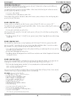
If PO2 reaches 1.60, the Audible will sound during which the PO2 value with icon will flash in place of Pressure (Fig. 65).
> After the Audible is silenced, the PO2 value with icon will alternate with Pressure once each minute*.
*PO2 will be displayed for 10 seconds, then Pressure will be displayed for 50 seconds once each minute until PO2 decreases below 1.60,
then PO2 will not be displayed.
Fig. 60 - VGM MAIN
(activated, during Audible)
Fig. 62 - VGM MAIN
(on surface < 10 min)
Fig. 61 - VGM MAIN
(after Audible)
Fig. 63 - PO2 WARNING
(during Audible)
Fig. 64 - PO2 ALARM
(during Audible)
(1) Up Arrow is Warning.
(2) Up Arrows is Alarm.
Fig. 65 - PO2 ALARM
(during Audible in Deco)
Summary of Contents for VT 4.0
Page 4: ...4 VT 4 0 OPERATING MANUAL 2002 Design 2011 Doc No 12 5213 r02 9 6 11 FEATURES FUNCTIONS...
Page 10: ...10 VT 4 0 OPERATING MANUAL 2002 Design 2011 Doc No 12 5213 r02 9 6 11 NORM SURFACE MODES...
Page 19: ...19 VT 4 0 OPERATING MANUAL 2002 Design 2011 Doc No 12 5213 r02 9 6 11 DIVE MODE FEATURES...
Page 24: ...24 VT 4 0 OPERATING MANUAL 2002 Design 2011 Doc No 12 5213 r02 9 6 11 NORM DIVE MODES...
Page 31: ...31 VT 4 0 OPERATING MANUAL 2002 Design 2011 Doc No 12 5213 r02 9 6 11 GAS TMT SWITCHING...
Page 34: ...34 VT 4 0 OPERATING MANUAL 2002 Design 2011 Doc No 12 5213 r02 9 6 11 GAUG OP MODE...
Page 39: ...39 VT 4 0 OPERATING MANUAL 2002 Design 2011 Doc No 12 5213 r02 9 6 11 FREE DIVE OP MODE...
Page 44: ...44 VT 4 0 OPERATING MANUAL 2002 Design 2011 Doc No 12 5213 r02 9 6 11 COMPASS MODE...
Page 55: ...55 VT 4 0 OPERATING MANUAL 2002 Design 2011 Doc No 12 5213 r02 9 6 11 TECHNICAL DATA...

