background image

4

CONTENTS (continued)

SETUP AND ACTIVATION ............................................................................................... 21

PRESSURE TRANSMITTER .................................................................................................................................... 22

ACTIVATION .............................................................................................................................................................. 22

Display Module Identification ............................................................................................................................... 24

SURFACE MODE ...................................................................................................................................................... 25

Accessing Other Modes ....................................................................................................................................... 26

SET MODES .............................................................................................................................................................. 26

ENTERING SETTINGS -SET MODE #1 ............................................................................................................... 27

ENTERING SETTINGS -SET MODE #2 ............................................................................................................... 30

PLAN AND DIVE MODES ................................................................................................ 45

TRANSMITTER SIGNAL RECEPTION GUIDE ........................................................................................................ 46

POSITIONING OF THE DISPLAY MODULE ............................................................................................................ 47
LINK INTERRUPTION UNDERWATER .................................................................................................................... 47
PRE DIVE PLANNING SEQUENCE ......................................................................................................................... 48

TISSUE LOADING BAR GRAPH .............................................................................................................................. 50

OXYGEN ACCUMULATION BAR GRAPH ............................................................................................................... 50

VARIABLE ASCENT RATE INDICATOR .................................................................................................................. 51

AIR TIME REMAINING BAR GRAPH ....................................................................................................................... 51

CONTROL OF DISPLAYS ......................................................................................................................................... 52

NO DECOMPRESSION DIVE MODE ....................................................................................................................... 53

No Decompression Dive Safety Stop ................................................................................................................... 54

DECOMPRESSION DIVE MODE ............................................................................................................................. 55

VIOLATION MODES .................................................................................................................................................. 57

Conditional Violation Mode .................................................................................................................................. 57

Delayed Violation Modes ..................................................................................................................................... 58

Immediate Violation Mode and Gauge Mode ...................................................................................................... 60

HIGH PO2 DIVE MODE ............................................................................................................................................. 61

HIGH OXYGEN ACCUMULATION ............................................................................................................................ 62

USER SET DIGITAL GAUGE MODE ........................................................................................................................ 63

Summary of Contents for VT Pro

Page 1: ...VT Pro dive computer operating manual OCEANIC...

Page 2: ...rating Mode g Icon Time h Variable Ascent Rate Indicator i Graphic Depth j Graphic Demo Mode k Icon Descend Arrow Icon Decompression Ceiling Icon Ascend Arrow l Icon Log Mode m Tissue Loading Bar Grap...

Page 3: ...h TLBG 11 Oxygen Bar Graph O2BG 11 Variable Ascent Rate Indicator VARI 12 Air Time Remaining Bar Graph ATRBG 12 DIVE TIME REMAINING 13 ALPHA NUMERIC DISPLAYS 13 Cylinder Pressure 13 Depth Displays 14...

Page 4: ...AY MODULE 47 LINK INTERRUPTION UNDERWATER 47 PRE DIVE PLANNING SEQUENCE 48 TISSUE LOADING BAR GRAPH 50 OXYGEN ACCUMULATION BAR GRAPH 50 VARIABLE ASCENT RATE INDICATOR 51 AIR TIME REMAINING BAR GRAPH 5...

Page 5: ...8 To access the Time to Fly Countdown 68 To access the Time to Desaturate Countdown 69 LOG MODE 69 AFTER THE FIRST 2 HOURS 72 WET CONTACTS 72 DOWNLOADING DATA TO A PC 73 RESET FEATURE 74 SIMULATOR DEM...

Page 6: ...6 WARNING Prior to diving with the VT Pro you must also read and understand the Oceanic Dive Computer Safety and Reference Manual Pay special attention to items marked with this Warning symbol...

Page 7: ...E U S Patents have been issued or applied for to protect the following design features Dive Time Remaining U S Patent no 4 586 136 Data Sensing and Processing Device U S Patent no 4 882 678 Air Time R...

Page 8: ...nd can radiate radio frequency energy and if not installed and used in accordance with the instructions may cause harmful interference to radio communications There is no guarantee that interference w...

Page 9: ...RNING Prior to diving with the VT Pro you must also read and understand the Oceanic Dive Computer Safety and Reference Manual which provides Important Warnings and Safety Recom mendations as well as g...

Page 10: ...r to diving with your VT Pro Remember that technology is no substitute for common sense and a dive computer only provides the person using it with data not the knowledge to use it INTERACTIVECONTROLCO...

Page 11: ...splays the one that is in control of your dive It is divided into a green No Decom pression normal zone a yellow Caution zone also No Decompression and a red De compression danger zone While you canno...

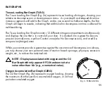
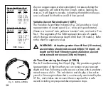
Page 12: ...should not exceed 60 fpm 18 mpm At depths of 60 feet 18 meters and shallower ascent rates should not exceed 30 fpm 9 mpm Air Time Remaining Bar Graph ATRBG The Air Time Remaining Bar Graph Fig 3b prov...

Page 13: ...Remaining which is a display that indicates the time that is more critical for you at that particular moment i e whichever time is the least amount available of the three Displayed will be either Time...

Page 14: ...format i e 1 16 represents 1 hour and 16 minutes not 116 minutes The colon that separates hours and minutes blinks once per second when the display is indicating real time e g Elapsed Dive Time and is...

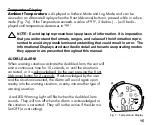
Page 15: ...in detail as the various operating modes they appear in are presented throughout this manual AUDIBLEALARM When warning situations activate the Audible Alarm the unit will emit a continuous tone for 1...

Page 16: ...lowable per dive limit or limit for a 24 hour period Ascending above a required Decompression ceiling stop depth for less than 5 minutes referred to as a Conditional Violation Ascent Rate exceeds 60 f...

Page 17: ...ural light present If a low level of light is present the Backlight will activate and illuminate the display for button depression time plus the user set Duration time of 0 3 or 7 seconds Press the bu...

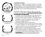
Page 18: ...ay Module the Battery icon and the Transmitter icon will then be dis played for 3 seconds indicating the condition of the Transmitter s Battery Fig 9B The display will then revert to Surface Mode If 7...

Page 19: ...gen related displays warnings and the O2 Bar Graph will not appear on the display for that dive or subsequent dives unless FO2 is set for a numerical value 21 50 Once a dive is made with the unit set...

Page 20: ...d the dives will be calculated based on 50 O2 50 nitrogen for oxygen calculations and 21 O2 79 nitrogen for nitrogen calculations If the Default function is set to OFF Fig 13 the FO2 value for repetit...

Page 21: ...RNING Prior to diving with the VT Pro you must also read and understand the Oceanic Dive Computer Safety and Reference Manual which provides Important Warnings and Safety Recom mendations as well as g...

Page 22: ...produced by other manufacturers Check with your Authorized Oceanic Dealer to verify compatibility with your Regula tor First Stage For the Display Module to receive a Tank Pressure signal from the Tra...

Page 23: ...ded Transmitter frequency Link and battery voltage to ensure that everything is within tolerance and functioning properly After manual activation it will also check the ambient baro metric pressure an...

Page 24: ...ion The Display Module was not set with the correct Link Code If the Transmitter signal is lost while on the surface the Display Module will stop searching for the signal after 10 minutes to save its...

Page 25: ...s are still wet it will reactivate and display the H2O graphic SURFACEMODE Surface Mode identified by the Surface Time icon Fig 19a follows Diagnostic Mode after Activation Information includes Dive N...

Page 26: ...ssed by first entering settings in Set Mode 1 or by bypassing Set Mode 1 Sequence is at the left Settings can be made one after the other or you can access a specific item that you want to set bypassi...

Page 27: ...ssed the unit will go to Simulator Demo Mode which is described on page 75 While in the Set Mode if neither button is pressed during a 2 minute period the unit will revert to Surface Mode ENTERING SET...

Page 28: ...e button to accept the setting and advance to Set Depth Alarm or press and hold Both buttons for 2 seconds to revert to Surface Mode TO SET MAX DEPTH ALARM while in the Surface Mode Factory set for 33...

Page 29: ...n in increments of 5 minutes Press Both buttons simultaneously release when SET 1 appears 2 seconds Press and release the Front Advance button FO2 appears with the set point value flashing Press the F...

Page 30: ...ntdown timer Fig 27 Download must be initiated before the timer reaches 00 within 2 minutes Download is initiated by the external device requesting data transfer i e the PC download program The unit r...

Page 31: ...the Front Advance button to accept the setting and advance to Set Hour Format or press and hold Both buttons for 2 seconds to revert to Surface Mode TO SET HOUR FORMAT while in the Surface Mode Facto...

Page 32: ...y release when SET 2 appears 4 seconds Press and release the Front Advance button the Units screen appears with the set point flashing Press the Front Advance button 2 more times Time appears with the...

Page 33: ...one Year Press the Front Advance button to accept the setting The Month value flashes Fig 33 Press and release the Side Select button to scroll through the Month values in increments of one month Pre...

Page 34: ...een appears with the set point flashing Press the Front Advance button 7 more times The graphic ALM and Alarm speaker icon appear with On or OFF flashing Fig 35 Press and release the Side Select butto...

Page 35: ...e to Set Air Time Remaining Alarm or press and hold Both buttons for 2 seconds to revert to Surface Mode TO SET ATRBG ALARM while in the Surface Mode Factory set for 5 minutes the Air Time Remaining B...

Page 36: ...000 PSI 69 to 205 BAR in increments of 250 PSI 17 BAR Press Both buttons simultaneously release when SET 2 appears Press and release the Front Advance button the Units screen appears with the set poin...

Page 37: ...The graphic End and Alarm speaker icon appear with the End Pressure Alarm value flashing Fig 40 Press and hold the Side Select button to scroll through the Alarm values in increments of 100 PSI 6 BAR...

Page 38: ...ont Advance button to accept the setting and advance to Set Max PO2 Alarm or press and hold Both buttons for 2 seconds to revert to Surface Mode TO SET MAXIMUM PO2 ALARM while in Surface Mode Factory...

Page 39: ...ts of this feature set ON or OFF are described on page 20 Press Both buttons simultaneously release when SET 2 appears 4 seconds Press and release the Front Advance button the Units screen appears wit...

Page 40: ...ith the Duration value flashing Fig 44 Press and release the Side Select button to advance the Duration from 00 to 03 to 07 seconds Press the Front Advance button to accept the setting and advance to...

Page 41: ...uttons for 2 seconds to revert to Surface Mode TO SET DIGITAL GAUGE MODE while in Surface Mode Factory set OFF Digital Gauge Mode can be set ON Once a dive is made with this feature set ON the setting...

Page 42: ...VT Pro will automatically Activate when immersed in water Press Both buttons simultaneously release when SET 2 appears 4 seconds Press and release the Front Advance button the Units screen appears wi...

Page 43: ...button the Units screen appears with the set point flashing Press the Front Advance button 19 more times 18 more times after a dive in Digital Gauge Mode The graphics tid and ON or OFF appear with On...

Page 44: ...h digit begins to flash Press and release the Side Select button to change the Fourth digit Press the Front Advance button to accept the Fourth digit The Fifth digit begins to flash Press and release...

Page 45: ...NING Prior to diving with the VT Pro you must also read and understand the Oceanic Dive Computer Safety and Reference Manual which provides Important Warnings and Safety Recom mendations as well as ge...

Page 46: ...46 Fig 50 Transmitter Signal Reception Guide Best Reception Area Poor Reception Area Poor Reception Area Poor Reception Area Poor Reception Area Poor Reception Distance greater than 3 feet 1 meter...

Page 47: ...st reception is achieved when the Display Module is within 3 feet 1 meter of the Trans mitter When installed into the high pressure port of the Regulator First Stage the Transmitter must be positioned...

Page 48: ...es adjusted dive times that are available for the next dive based on residual nitrogen or oxygen accumulation which ever is in control following the last dive and surface interval The PDPS provides a...

Page 49: ...ted to be nitrogen controlled or predicted oxygen tolerance limits OTLs based upon either a single dive exposure or your 24 hour accumulation of oxygen if calculated to be oxygen controlled The Maximu...

Page 50: ...est dive completed TISSUE LOADING BAR GRAPH Fig 54a As your Depth and Elapsed Dive Time increase the Tissue Loading Bar Graph TLBG will add segments green toward red to represent the absorption of nit...

Page 51: ...meters minute At depths of 60 feet 18 meters and shallower maximum recommended rate is 30 feet minute 9 meters minute AIR TIME REMAINING BAR GRAPH The Air Time Remaining Bar Graph ATRBG Fig 56a displ...

Page 52: ...play An exception to this is during a No Decompression dive Safety Stop described on page 54 During Cautionary situations e g Decompression High PO2 etc there is a Main Default Display of important in...

Page 53: ...epth for that dive and icon Elapsed Dive Time and icon Dive Time Remaining and Mode icon Tank Pressure and the applicable bar graphs Press and release the Front Advance button again to view Display 3...

Page 54: ...3 seconds then revert back to the Main Display previously selected 1 4 No Decompression Dive Mode SAFETY STOP Fig 63 Upon ascending to 20 feet 6 meters on any No Decompression dive in which depth exc...

Page 55: ...seconds unless set OFF or until acknowledged Press and hold the Front Advance button for 2 seconds to acknowledge silence the Audible Alarm unless set OFF The UP Arrow and Deco Bar will flash if you...

Page 56: ...can slowly ascend to but not shallower than that indicated Ceiling Stop Depth To view Alternate Displays of information press and release the Front Advance button They revert to the Main Default Disp...

Page 57: ...be accessed using the Front Advance button and the Backlight can be activated using the Side Select button To view the Alternate Displays of information similar to Deco screens press and release the...

Page 58: ...lty Time is worked off and off gassing credit begins required decompression Stop Depths and Time will decrease toward zero The Tissue Loading Bar Graph will recede into the yellow Caution Zone and the...

Page 59: ...n and stay as close as possible to 60 feet 18 meters without causing the Total Ascent Time display to flash When the Required Stop Depth indicates 50 FT 15 M etc you can ascend to those depths and con...

Page 60: ...the remain der of that dive and for 24 hours after surfacing Gauge Mode turns the VT Pro into a digital instrument without any decompression or oxygen monitoring functions Only Current Depth Max Dept...

Page 61: ...made during the 24 hour period a full 24 hour surface interval must then be served before all functions are restored HIGH PO2 DIVE MODE When partial pressure of oxygen PO2 becomes equal to or greater...

Page 62: ...The unit will revert to the Main Default Display after 3 seconds Press the Side Select button to activate the Backlight HIGHOXYGENACCUMULATION The O2 Bar Graph displays either oxygen accumulated duri...

Page 63: ...button to view the Alternate Displays The unit will revert to the Main Default Display after 3 seconds Press the Side Select button to activate the Backlight USER SET DIGITAL GAUGE MODE When Digital...

Page 64: ...important reason for not pushing the no decompression and oxygen accumulation limits and a critical reason to avoid entering decompression If you dive in situations where your trip would be ruined or...

Page 65: ...NG Prior to diving with the VT Pro you must also read and understand the Oceanic Dive Computer Safety and Reference Manual which provides Impor tant Warnings and Safety Recommendations as well as gene...

Page 66: ...ve Time Information displayed includes Fig 80 Number of that dive during that activation period Temperature ambient Time of Day and icon Surface Interval time colon flashing and Mode icon flashing Tan...

Page 67: ...Transition Period on the surface is completed Once 10 minutes have elapsed the Surface Mode icon and Surface Interval time display colon stop flashing indicating that the Dive and Transition Period a...

Page 68: ...d oxygen calculated to be remaining from the previous dives To access the Time to Fly Countdown while in Surface Mode Press the Front Advance button 2 times The Time to Fly counter Fig 84 begins count...

Page 69: ...est 24 dives is stored in the Log for viewing The first dive of a new activation period will be 1 then 2 etc After 24 dives are accumulated each subsequent dive will overwrite the oldest dive in the L...

Page 70: ...ve To return to Surface Mode at any time while in Log Mode press Both buttons simultaneously for 2 seconds The unit will automatically revert to Surface Mode after 2 minutes if no button is pressed wh...

Page 71: ...tissue nitrogen loading at the time you surfaced at the end of the dive Also the segment that reflects the maximum loading during the dive will appear flashing To view the Third Screen of the Log Oxy...

Page 72: ...aphic H2O appears during the Fly Mode Fig 90 and Desaturation Mode Fig 91 countdowns that alternate 2 hours after a dive it is an indication that the water activation contacts are bridged still wet an...

Page 73: ...wnload package that is available from your Authorized Oceanic Dealer The software program provides dive tabular and graphic profile data sampled throughout the dives at the interval you set NOTE Ensur...

Page 74: ...t Advance button 1 time to access PLAN MODE While 30 feet 9 meters is displayed in the PLAN MODE press and hold Both buttons until SET 2 appears then release the buttons and press the Front Advance bu...

Page 75: ...NING Prior to diving with the VT Pro you must also read and understand the Oceanic Dive Computer Safety and Reference Manual which provides Impor tant Warnings and Safety Recommendations as well as ge...

Page 76: ...auge Mode to be set ON or OFF calculations to be cleared and FO2 to be set Access and Setup while in real Surface Mode Press and hold Both buttons for 6 seconds Release the buttons during the 2 second...

Page 77: ...om previous actual dives Subsequent repetitive Simulated dives do not take into consideration previous Simulated dives Press and release the Side Select button to toggle between NEW and CUR Press and...

Page 78: ...X and PO2 Press and hold the Side Select button to scroll from Air to 21 through 32 in 1 increments The scroll will stop when the button is released or at 32 Press and hold the Side Select button agai...

Page 79: ...s release the Side Select button during the Descent to stop the Descent Tap press release the Front Advance button during the Descent or stopped to access the Alternate Displays Press and hold the Sid...

Page 80: ...vance button for 2 seconds The red segment of the VARI and an outer UP Arrow around the small one will appear flashing Fig 103 The Alarm will sound and the red LED will flash Pressing and holding the...

Page 81: ...me rate to normal FO2 can be set 10 minutes after surfacing Tap press release the Front Advance button to access FO2 Set Mode The FO2 graphic and value previously set will appear with the value flashi...

Page 82: ...82 R E S P O NSIBLE D I V E R Be a RESPONSIBLE DIVER at all times...

Page 83: ...rior to diving with the VT Pro you must also read and understand the Oceanic Dive Computer Safety and Reference Manual which provides Impor tant Warnings and Safety Recommendations as well as general...

Page 84: ...ewarm water or a slightly acidic white vinegar water bath After removal from the bath place the Display Module and the Regulator with Transmitter unit under gently running water and towel dry before s...

Page 85: ...reason for return your name address day time phone number serial number and a copy of your original sales receipt and Warranty Registration Card Send freight prepaid and insured using a traceable met...

Page 86: ...s be changed in an environment equivalent to the local outdoor temperature and humidity e g do not change the Battery s in an air conditioned environment then take it outside during a hot sunny day In...

Page 87: ...oles in the Ring Fig 106B Lift the Hatch Ring up and away from the Housing Remove the clear Battery Hatch Battery Removal Remove the Retaining Bar located across the lower portion of the Battery Fig 1...

Page 88: ...If damage or corrosion is found return your Versa Pro to an Authorized Oceanic Dealer and DO NOT attempt to use it until it has received factory prescribed service Remove the Battery Hatch O ring s a...

Page 89: ...th a hair dryer set at no heat Display Module Battery Installation Slide a new 3 volt type CR2450 Lithium Battery negative side down into the Battery Cavity Slide it in from the right side and ensure...

Page 90: ...wise 5 degrees until the tabs engage then tighten it 5 more degrees by turning it counter clockwise with the aide of a small blade screwdriver or spanner tool pressing against the upper left arm of th...

Page 91: ...ure The outer surface of the Battery Hatch should be flush with the outer surface of the Housing Testing Pressurize the Regulator Assembly and Transmitter Activate the Display Module and watch careful...

Page 92: ...egulator s HP Port and tighten until secure with a 5 8 open end wrench Attach the Regulator First Stage to a full Scuba Tank and pressurize by slowly opening the Tank Valve listening for any indicatio...

Page 93: ...ivation Diagnostic Reset Surface Plan 30 190 feet 9 57 meters Time to Fly Countdown Desaturation Countdown Dive Log Date Time Nitrogen and Oxygen Set Mode 1 FO2 Air 21 to 50 O2 Max Depth Alarm 30 to 3...

Page 94: ...maining Cylinder Pressure Bar Graphs Digital Gauge Mode Default Current Depth Max Depth Time of Day Elapsed Dive Time Cylinder Pressure Bar Graphs Secondary Current Depth Air Time Remaining Cylinder P...

Page 95: ...Stop Time 0 00 to 9 59 hr min 1 minute Elapsed Dive Time 0 00 to 9 59 hr min 1 minute Surface Time 0 00 to 23 59 hr min 1 minute Dive Log Surface Interval 0 00 to 23 59 hr min 1 minute Time to Fly 23...

Page 96: ...s min 0 0 10 0 3 0 0 20 0 6 Normal Zone Green 1 11 15 3 5 4 5 1 21 30 6 5 9 Normal Zone Green 2 16 20 5 6 2 31 40 9 5 12 Normal Zone Green 3 21 25 6 5 7 5 3 41 50 12 5 15 Caution Zone Yellow 4 26 30 8...

Page 97: ...ife expectancy 50 dive hours if 1 1 hour dive per dive day to over 150 dive hours if 3 1 hour dives per dive day Battery Indicator segments displayed estimated power remaining all 25 to 100 1 inside 2...

Page 98: ...etween 20 F and 140 F 6 and 60 C In the water between 28 F and 95 F 2 and 60 C At extremely low temperatures the LCD may become sluggish but this will not affect it s accuracy If stored or transported...

Page 99: ...info oceanicuk com Oceanic France Marseille France Tel 33 491 25 27 45 Fax 33 491 25 35 86 E mail oceanicfrance wanadoo fr Oceanic International Pacific Kapolei Hawaii Tel 808 682 5488 Fax 808 682 106...

Page 100: ...rialNumber _______________________ Date of purchase _____________________ Purchasedfrom ______________________ Below to be filled in by an Authorized Oceanic Dealer R E S P O NSIBLE D I V E R Date Ser...

Page 101: ...101 NOTES...

Page 102: ...OCEANIC USA 2002 Davis Street San Leandro CA 94577 Tel 510 562 0500 Fax 510 569 5404 http www OceanicWorldWide com 2002 Design 2002 Doc No 12 2338 r02 2 3 03...

Reviews: