


20
Chapter 5.2: Installation of V AC Power Supplies
Additional items required (not supplied)
• Screws to secure the driver
• Junction box / waterproof connectors
• Sufficient cable to connect to power lead.
• Suitable fuse / breaker(s)
Connecting lights to your AC power source
Warning
: Always consult a qualified electrician when connecting OceanLED light fixtures.
Warning
: Never use power tools to secure the drivers: hand tighten only.
Warning
:
Brown=Live; Blue=Neutral; Green/Yellow=Earth
Warning
: When connecting light units, please note that all OceanLED lights will operate within a specific
voltage range. Please check the electrical information to ensure cable gauge, fuse recommendations, breaker
size etc.
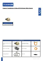
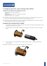
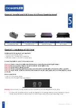
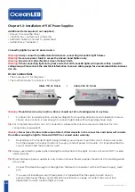
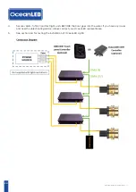
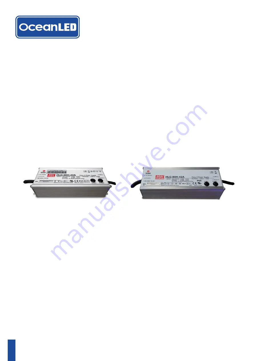
Driver connections
• The 3 core input is for the power
• The multi pin Deutsch connector is for the light.
Allure 150 AC Driver | Allure 250 AC Driver
Warning
:
Mount drivers in a dry location. Drivers should not sit in standing water at any time.
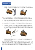
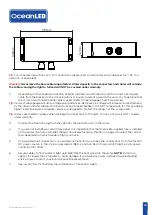
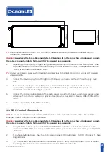
1.
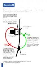
Fix driver into required position, see below diagram for mounting dimensions and clearances. Ensure
chosen driver location is near enough to connect light cable without applying undue stress.
Tip
: For complete instructions on V AC connections, please refer to local codes and ordinances for V AC
connections or equivalent.
Warning
: Never leave the bare cables unprotected. Water deposits in the connectors and cables will corrode
the cables causing the light to fail and will NOT be covered under warranty.
2.
Depending on the model of lights being installed you will need to pull the correct sized power cable
from the breaker to the driver locations to supply constant power to the units. It is imperative that the
correct sized tinned marine cable is used.
Tip
: Always use dielectric grease when making the connections to the light. Corrosion of wire is NOT covered
under warranty.
Tip
: Mount all drivers/power supplies in a dry location. Drivers/Power supplies should not sit in standing water
at any time.
3.
Connect the Deutsch plug from the light into the Deutsch connector on the AC Power Supply (multi
pin).
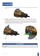
4.
If you are not installing a custom fuse panel, it is imperative that the supply to each driver is
appropriately fused. Please consult electrical specification on page 4 to select the correct fuse
dependant on which model of light you have.
OceanLED INSTALL / ALLURE / 240717 / 7.1