


77
2
CHAPTER
TWO
Chapter 2: Preparing the Hull
Note:
OceanLED makes every effort to protect our marine and fresh water
environment as well as our natural resources. Please take care to keep packaging away from
and out of the water by ensuring loose packaging materials are secured and not susceptible
to being blown into the water. Please recycle all packaging materials as the sustainability of our
environment is everyone’s responsibility.
Warning
: There are several different hull types most are either solid fiberglass or cored. Be sure you follow
the correct procedures for the hull you are preparing since all require different preparation methods.
We will cover the two most common types below. If in doubt please contact your local OceanLED
representative or the boat manufacturer for assistance.
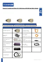
Warning
: Please check all components prior to installation. If there is any damage to connectors, cables,
and/or any other component, please notify OceanLED BEFORE installation.
Additional tools needed that are not provided by OceanLED
•
Power drill (with a hole saw sized to suit your light model, see below)
•
Sand Paper
•
Filler (reference boat manufacturer's specifications)
2.1 Preparing a Solid Fiberglass Hull
Tip
: Always wear safety goggles and a dust mask.
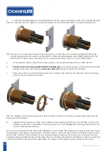
1.
Drill a 3mm / 1/8” pilot hole perpendicular to the waterline from inside the hull. If there is a rib, strut,
or other hull irregularity near the selected mounting location, this will need to be taken into account
in the planning phase and the location adjusted accordingly, or the obstruction safely removed or
modified.
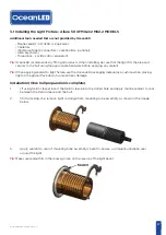
2.
Using the correct sized hole saw (see table below), cut the mounting hole from outside the hull. Be
sure to hold the drill plumb, so the hole will be perpendicular to the surface of the hull.
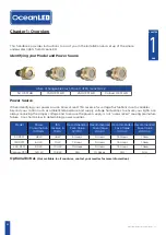
Solid and Cored Hull Installation Saw Size
Product Name
Metric
Imperial
50 XFM HD Gen2
60.5mm
2.38”
150 XFM HD Gen2
83mm
3.25”
250 XFM HD Gen2 / Colours XFM 83mm
3.25”
TIP:
If drilling large holes, alternate between applying pressure to the drill and relaxing the action to ensure
an even cut through the hull and the saw’s longevity. If cutting through Kevlar shield or metal, be
careful of overheating the hole saw.
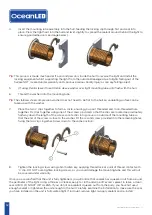
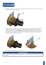
3.
Sand the area around the hole using a heavy grit sandpaper to remove the previous bottom paint
and to ensure that the sealant will adhere properly to the hull. If there is any petroleum residue
inside the hull, remove it with acetone before sanding.
OceanLED INSTALL / ALLURE / 240717 / 7.1


