background image

EXPLORE 

E2

.


INSTALL & OPERATION MANUAL 


17 


EXPLORE SERIES


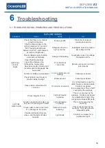
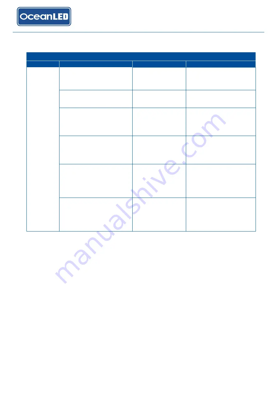
PROBLEM


CHECK


CAUSE


FIX


Light does not 

light up 

Check that the electrical 

connections between the light 

and the supply cable have been 

made correctly 

Poor electrical 

connection 

Remake connection and seal 

joint correctly 

Check that the wiring polarity is 

correct, red to positive and 

black to negative 

Polarity incorrect 

Change the wiring polarity 

and seal joint correctly 

Check that there is power 

supply to the light cable 

connection 

Poor electrical 

connection 

Trace the cables back, 

checking at joints until break 

has been located. Then rectify 

the problem and seal joint 

correctly 

Check that the electrical 

connections between the supply 

cable and the light circuit 

breaker or fuse have been 

made correctly 

Poor electrical 

connection 

Remake connection and seal 

joint correctly 

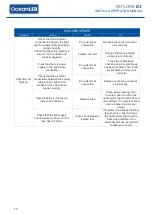
Check that the in-line fuse is 

intact and not blown 

Replace fuse 

If fuse keeps blowing, then 

there is a short circuit in the 

light system that must be traced 

and rectified. If no external short 

can be located contact your 

dealer 

Check that the light supply 

circuit breaker is closed, or the 

fuse has not blown 

Close circuit breaker / 

replace fuse 

If breaker / fuse keeps blowing, 

then there is a short circuit in 
the light system that must be 

traced and rectified. If no 

external short can be located 

contact your dealer 


Summary of Contents for EXPLORE E2

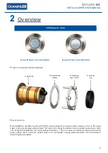
Page 1: ...LIGHT YEARS AHEAD WWW OCEANLED COM OceanLED MANUAL EXPLORE SERIES E2 REVISION 1 INSTALLATION OPERATION MANUAL EXPLORE E2 ...

Page 2: ...ain combinations of plastic and polymer products which are impervious to saltwater corrosion however screws and fasteners used for the installation must be of a marine grade type stainless steel or equivalent and monitored annually to ensure the lights remain in service for years to come Never connect disconnect lights with power applied as irreversible damage may occur Ensure polarity of power co...

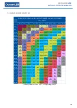
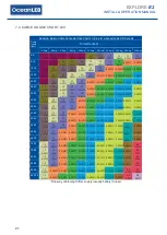
Page 3: ...16 7 Appendix 18 7 1 OVERALL DIMENSIONS 18 7 2 ESSENTIAL TEST 19 7 3 CABLE GAUGE CHART 12V 20 7 4 CABLE GAUGE CHART 24V 21 8 Warranty 22 PRETEST Always test the lights prior to installation Failure to do this may result in additional installation time and could invalidate the warranty Never leave lights ON out of water for longer than 5 minutes followed by an off period of 1 hour IMPORTANT NOTICE ...

Page 4: ...ne sealant applied evenly around bezel Ensure fully watertight seal is created after sealant cures 6 Correct clamping of light fixture onto hull Never leave vessel unchecked for a few days after install Always check routinely for a few days after installation to ensure the install is correct and fully sealed 7 Light s correctly bonded and vessel bonding system check carried out refer to relevant s...

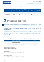
Page 5: ...e fluctuations due to variables beyond your control such as ambient temperature and supply voltage fluctuations This is to ensure your lights are always receiving the proper voltage and to ensure the power supply is not overloaded causing premature failure Use chart below in determining power supplies Identifying your model Explore E2 Single Colour Narrow Beam Explore E2 Single Colour Wide Beam A ...

Page 6: ...detail on modifications and installation If lights are assembled in a conductive or wooden hull an Isolation Kit must be used Contact OceanLED for additional details Depth Spacing Ideally mount your lights at similar depth levels to ensure matching colour consistency through the water Deeper lights will look duller and possibly differ in colour compared to shallower mounted units SPACING INSTALL D...

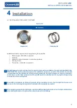
Page 7: ... the introduction of potential contaminants that may damage the product and void warranty The light cartridge can only be removed for maintenance or after sales purposes and OceanLED must be contacted prior to any light cartridge being removed from the mounting tube OceanLED recommends dry fitting all products When installing be sure that the light fits the area and secures to the hull using the a...

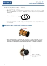
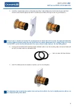
Page 8: ...ear of the mounting tube assembly s bezel to ensure a complete unbroken seal around the light Make sure sealant fills in the recess groove on the reverse of the light bezel 4 Ensure the light orientation is correct with the cable gland at the back positioned at the bottom see image below perpendicular to thewaterline If there is not enough space at the back of the light for the cable the light ori...

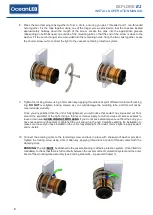
Page 9: ... supporting the light from the outside Breakages due to lights falling out of the hull are NOT covered under warranty and can cause serious bodily injury as can any falling object 6 If using a Delrin Isolation Kit insert the Isolation Kit Rear washer over the mounting tube and locate it flush with the hull The Rear washer is identified as flat 7 Insert the stainless steel compression washer over t...

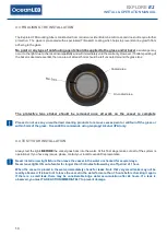
Page 10: ...warranty Once you are satisfied that the unit is fully tightened you will notice that sealant has squeezed out from around the perimeter of the light Using a thinner or cleaner apply to cloth and wipe off excess sealant to leave a clean seal AVOID CONTACT WITH LENS If you do not see sealant squeeze out from the body you have not used enough sealant or tightened the unit enough to the hull Carefull...

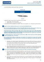
Page 11: ... cable runs to the switch location 1 Depending on the model and number of lights installed you will need to pull the correct sized power cable from the DC power source breaker fuse panel to the light locations to supply constant power to the light units It is imperative that the correct sized tinned marine grade cable is used to avoid voltage drop issues See Chapter 7 Appendix for recommended cabl...

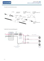
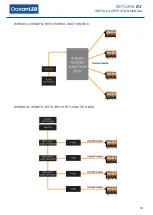
Page 12: ...Kit Connection Overview 12 24V DC Connection Diagram FUSE OPTIONAL PUSH TO BREAK SWITCH NOT SUPPLIED FUSE FUSE POWER SWITCH NOT SUPPLIED FUSE BREAKER NOT SUPPLIED RED BLACK 2M 79 LIGHT CABLE DC CABLE TO POWER SOURCE NOT SUPPLIED EXPLORE E2 LIGHTS ...

Page 13: ...EXPLORE E2 INSTALL OPERATION MANUAL 12 WIRING SCHEMATIC WITH POWER JUNCTION BOX WIRING SCHEMATIC WITH 3RD PARTY JUNCTION BOX ...

Page 14: ...eaning products to remove excess paint or antifoul off the glass or within 5mm of the glass OceanLED recommends using Isopropyl Alcohol IPA only 4 4 TEST YOUR INSTALLATION Always test the lights BEFORE the vessel goes back into the water At this final stage make sure all of the system is operational If you have any issues please contact your local OceanLED representative Never install a new light ...

Page 15: ...h pressure jet wash to clean the lens bezel as this will damage the seals and void the warranty 5 3 LIGHT CARTRIDGE REMOVAL Before proceeding with this operation you MUST seek permission from either the manufacturer or your OceanLED representative or you will void the warranty DO NOT remove the light cartridge from the mounting tube during installation The light cartridge MUST stay fitted inside t...

Page 16: ... help to insert the light cartridge be needed OceanLED recommend the use of a small quantity of Isopropyl Alcohol sprayed onto the O Ring on the back of the light cartridge 1 Inspect the mounting tube and light cartridge to ensure no contaminant grease debris dirt and or water are present 2 Undo the cable gland to act as a breather Failure to do so will make the installation process significantly ...

Page 17: ...ke connection and seal joint correctly Confirm all LEDs are illuminated 1 or more LEDs are not working Contact your dealer Check lights to see if water is present inside the light Water present Contact your dealer Check cable connections for corrosion If corrosion is present It is not advised to reuse the cable if water is present inside Contact your dealer for a replacement This is NOT covered by...

Page 18: ...s been located Then rectify the problem and seal joint correctly Check that the electrical connections between the supply cable and the light circuit breaker or fuse have been made correctly Poor electrical connection Remake connection and seal joint correctly Check that the in line fuse is intact and not blown Replace fuse If fuse keeps blowing then there is a short circuit in the light system th...

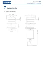
Page 19: ...EXPLORE E2 INSTALL OPERATION MANUAL 18 7 Appendix 7 1 OVERALL DIMENSIONS ...

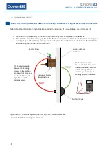
Page 20: ...eading of up to 0 5Ω Ohms This procedure will guarantee electrical continuity between the front bezel the mounting tube and the sacrificial anode If you have any questions regarding the above please contact OceanLED 44 0 1455 637505 or info oceanled com Aluminium Bronze Front Bezel Bonding Screw Aluminium Bronze Mounting Tube Sacrificial Anode YES NO The Resistance reading between the bonding scre...

Page 21: ... 8 AWG 6 AWG 6 AWG 4 AWG 2 AWG 2 AWG 1 AWG 0 AWG 2 0 AWG 40 45 12 AWG 10 AWG 8 AWG 6 AWG 4 AWG 4 AWG 2 AWG 2 AWG 1 AWG 0 AWG 2 0 AWG 45 50 12 AWG 8 AWG 6 AWG 6 AWG 4 AWG 2 AWG 2 AWG 1 AWG 0 AWG 2 0 AWG 3 0 AWG 50 55 12 AWG 8 AWG 6 AWG 6 AWG 4 AWG 2 AWG 2 AWG 1 AWG 0 AWG 2 0 AWG 3 0 AWG 55 60 10 AWG 8 AWG 6 AWG 4 AWG 4 AWG 2 AWG 1 AWG 0 AWG 0 AWG 3 0 AWG 4 0 AWG 60 65 10 AWG 8 AWG 6 AWG 4 AWG 4 AWG...

Page 22: ...10 AWG 10 AWG 8 AWG 6 AWG 6 AWG 4 AWG 4 AWG 2 AWG 2 AWG 40 45 14 AWG 12 AWG 10 AWG 10 AWG 8 AWG 6 AWG 4 AWG 4 AWG 4 AWG 2 AWG 2 AWG 45 50 14 AWG 12 AWG 10 AWG 8 AWG 8 AWG 6 AWG 4 AWG 4 AWG 2 AWG 2 AWG 1 AWG 50 55 14 AWG 12 AWG 10 AWG 8 AWG 8 AWG 6 AWG 4 AWG 4 AWG 2 AWG 2 AWG 1 AWG 55 60 14 AWG 10 AWG 10 AWG 8 AWG 6 AWG 4 AWG 4 AWG 2 AWG 2 AWG 1 AWG 0 AWG 60 65 14 AWG 10 AWG 8 AWG 8 AWG 6 AWG 4 AWG...

Page 23: ...rved Specifications are subject to change without notice Trademarks are the property of Ocean LED Marine LTD www oceanled com Ocean LED Marine LTD Ocean LED USA LLC Unit 1 Jacknell Road Dodwells Bridge Industrial Estate Hinckley Leicestershire LE10 3BS United Kingdom 778 South Military Trail Deerfield Beach Florida FL 33442 3025 USA Tel 44 0 1455 637505 Fax 44 0 1455 238553 sales oceanled com Tel ...

Reviews: