
EXPLORE
E2
.
INSTALL & OPERATION MANUAL
4
2
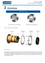
Overview
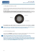
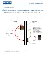
Product components breakdown
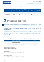
Power Source
Most installations will utilize on-board 12/24V DC power supply from a marine battery. However, if AC to DC power
supply is being used, please allow at least 15% reserve for voltage fluctuations due to variables beyond your control
such as ambient temperature and supply voltage fluctuations. This is to ensure your lights are always receiving the
proper voltage and to ensure the power supply is not
“overloaded”, causing premature failure. Use chart below in
determining power supplies.
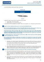
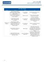
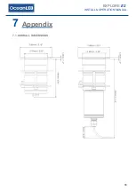
Identifying your model
Explore E2 Single Colour Narrow Beam
Explore E2 Single Colour Wide Beam
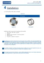
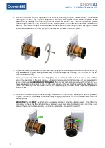
A- Light Unit
C- Compression
washer
D- Clamping
clips + bolts
E- Locking
ring


