background image


Document UT-MT-0699 

Page 1 of 27 

Via della Solidarietà, 2/1 
40056 Valsamoggia Loc. Crespellano 
BOLOGNA    ITALY


Edition 16/03/2020 

Supersedes edition 12/02/2019


  Via della Solidarietà 2/1 – 40056 Valsamoggia - Italy 


THIS COPY IS NOT SIGNED SINCE IT IS FILED AND DELIVERED BY MEANS OF THE AUTOMATIC KNOWLEDGE MANAGEMENT SYSTEM (IT CAN BE SIGNED ON REQUEST). THIS DOCUMENT AND THE DATA CONTAINED HERE IN, IS 

PROPRIETARY PROPERTY AND SHALL NOT BE DUPLICATED, USED OR DISCLOSED – IN WHOLE OR IN PART – FOR ANY PURPOSE WITHOUT WRITTEN CONSENT OF OCEM.


LED LUMINOUS GUIDANCE SIGN 


LIGS01 


INSTRUCTION MANUAL FOR USE, INSTALLATION 

AND MAINTENANCE


Compiled by: M.Romagnoli 

Approved by: M.Mazzotti 


N° Attachments: 1 

Copy n°: 


Summary of Contents for LIGS01

Page 1: ...LED AND DELIVERED BY MEANS OF THE AUTOMATIC KNOWLEDGE MANAGEMENT SYSTEM IT CAN BE SIGNED ON REQUEST THIS DOCUMENT AND THE DATA CONTAINED HERE IN IS PROPRIETARY PROPERTY AND SHALL NOT BE DUPLICATED USE...

Page 2: ...wo size tables transformers case SCR and Sinusoidal 26 07 2016 Correct the document code 20 05 2016 Added option 10 23 11 2015 Added attachment 1 for special version 17 07 2013 Updated power consumpti...

Page 3: ...6 3 MAIN FEATURES 6 3 1 Environmental Data 6 3 2 Electrical Data 7 3 2 1 Current Power Supply 7 3 2 2 Voltage power Supply 8 3 3 Luminance Data 9 3 4 Description of the Signs 9 3 4 1 Main Structure 9...

Page 4: ...V Sign Single Faced Wiring Diagram 22 Figure 10 3 MODULES 230V 37V Sign Single Faced Wiring Diagram 23 Figure 11 4 MODULES 230V 37V Sign Single Faced Wiring Diagram 24 Figure 12 4 MODULES Signs with O...

Page 5: ...to 6 6 A 3 step CCR or fixed at 6 6 A 1 step CCR The power to be used for sizing the isolation transformer and the CCR depends on the length of the sign and are shown in chapter 3 2 1 Voltage Power su...

Page 6: ...sion FAA mode 3 483 km h 55 Protection degree IP55 69 Orange rear side for single face signs ENAC only 70 Bird Spikes 71 ON OFF Key switch D2 Supply voltage an external 230 37 Vac transformer is requi...

Page 7: ...R RATING W to the currents of Sign modules 1 2 3 4 6 6A 65 150 200 300 4 8 6 6A 100 150 300 300 2 8A 6 6A STANDARD 150 300 400 500 Opt 18 2x300 SIZE TRANSFORMERS case Sinusoidal TRANSFORMER RATING W t...

Page 8: ...ology The minimum rating of the transformers 230V 37V 50Hz are SIGN MODULES 1 2 3 4 TRANSFORMER RATING VA 60 110 160 220 Table 1 Rating of the transformers 230V 37V 50Hz The Power absorbed by each sig...

Page 9: ...actured by other Companies 3 4 Description of the Signs The signs practically include the following sections see Figure 1 a main structure b panels for faces c LEDs luminous source d electronic boards...

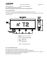
Page 10: ...loured translucent films applied to the internal side of the panel Number of Modules 1 2 3 4 A 991 1976 2961 3946 Legend Height 300 400 B 838 1038 Figure 1 Overall Dimensions 3 4 3 LEDs Luminous Sourc...

Page 11: ...in the supply with G 2 threaded lower section 3 4 4 2 Voltage Power Supply In case of voltage supply the sign is equipped with an AC voltage DC current converter consisting of an electronic board hou...

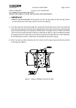
Page 12: ...e walled accurately as shown in Figure 2 and in manner to assure the parallelism of the centreline marked on the flange and the sign centreline f Remove the frangible couplings floor flanges from the...

Page 13: ...with plug of the sign to the socket of the isolating transformer be sure that the cable lead with plug be passed through the coupling for flexible pipe The plug socket connection should be secured ins...

Page 14: ...2016 LED LUMINOUS GUIDANCE SIGN LIGS01 INSTRUCTION MANUAL FOR USE INSTALLATION AND MAINTENANCE Number of Modules DIMENSION 1 2 3 4 A 991 1976 2961 3946 A 955 1940 2925 3910 T 3366 4351 5336 6321 Lege...

Page 15: ...comes necessary follow the procedure below a Be sure that the series circuit is de activated regulator unit CCR off or Main switch of the 230Vac line open according to the type of sign in any case tur...

Page 16: ...ant four screws c Check the wiring the connection to the terminal strips and the continuity d If necessary replace the power supply board e Mount the top cover with reverse procedure f Turn the main s...

Page 17: ...nt UT MT 0699 Page 17 di 27 Edition 12 02 2019 Supersedes edition 26 07 2016 LED LUMINOUS GUIDANCE SIGN LIGS01 INSTRUCTION MANUAL FOR USE INSTALLATION AND MAINTENANCE Figure 4 1 MODULE Signs Wiring Di...

Page 18: ...nt UT MT 0699 Page 18 di 27 Edition 12 02 2019 Supersedes edition 26 07 2016 LED LUMINOUS GUIDANCE SIGN LIGS01 INSTRUCTION MANUAL FOR USE INSTALLATION AND MAINTENANCE Figure 5 2 MODULES Signs Wiring D...

Page 19: ...nt UT MT 0699 Page 19 di 27 Edition 12 02 2019 Supersedes edition 26 07 2016 LED LUMINOUS GUIDANCE SIGN LIGS01 INSTRUCTION MANUAL FOR USE INSTALLATION AND MAINTENANCE Figure 6 3 MODULES Signs Wiring D...

Page 20: ...nt UT MT 0699 Page 20 di 27 Edition 12 02 2019 Supersedes edition 26 07 2016 LED LUMINOUS GUIDANCE SIGN LIGS01 INSTRUCTION MANUAL FOR USE INSTALLATION AND MAINTENANCE Figure 7 4 MODULES Signs Wiring D...

Page 21: ...T MT 0699 Page 21 di 27 Edition 12 02 2019 Supersedes edition 26 07 2016 LED LUMINOUS GUIDANCE SIGN LIGS01 INSTRUCTION MANUAL FOR USE INSTALLATION AND MAINTENANCE Figure 8 1 MODULE 230V 37V Signs Wiri...

Page 22: ...MT 0699 Page 22 di 27 Edition 12 02 2019 Supersedes edition 26 07 2016 LED LUMINOUS GUIDANCE SIGN LIGS01 INSTRUCTION MANUAL FOR USE INSTALLATION AND MAINTENANCE Figure 9 2 MODULES 230V 37V Signs Wiri...

Page 23: ...MT 0699 Page 23 di 27 Edition 12 02 2019 Supersedes edition 26 07 2016 LED LUMINOUS GUIDANCE SIGN LIGS01 INSTRUCTION MANUAL FOR USE INSTALLATION AND MAINTENANCE Figure 9 3 MODULES 230V 37V Signs Wiri...

Page 24: ...MT 0699 Page 24 di 27 Edition 12 02 2019 Supersedes edition 26 07 2016 LED LUMINOUS GUIDANCE SIGN LIGS01 INSTRUCTION MANUAL FOR USE INSTALLATION AND MAINTENANCE Figure 10 4 MODULES 230V 37V Signs Wir...

Page 25: ...0699 Page 25 di 27 Edition 12 02 2019 Supersedes edition 26 07 2016 LED LUMINOUS GUIDANCE SIGN LIGS01 INSTRUCTION MANUAL FOR USE INSTALLATION AND MAINTENANCE Figure 11 4 MODULES Signs with OPTION 18...

Page 26: ...LIGS RISLG0022 Ric Breakable coupling Kit Tab 3M H300 LIGS RISLG0021 Ric Breakable coupling Kit Tab 2M H300 LIGS RISLG0020 Ric Breakable coupling Kit Tab 1M H300 LIGS RISLG0019 Ric PANN TAB 4M S4 H60...

Page 27: ...elbow 013 0008 Galvanized steel pipe elbow with upper threaded end only 315 3210 Galvanized steel pipe elbow with both threaded ends 315 1228 Base L 867 Class I Size B 24 deep 315 1062 Baseplate for...

Reviews: