background image


Document UT-MT-0428 

Page 15 of 35 


Edition 11/03/2014 

Supersedes edition 04/30/2012 


INSET RUNWAY EDGE LIGHT SLRE 
INSTRUCTION MANUAL FOR USE, INSTALLATION AND MAINTENANCE 


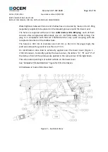
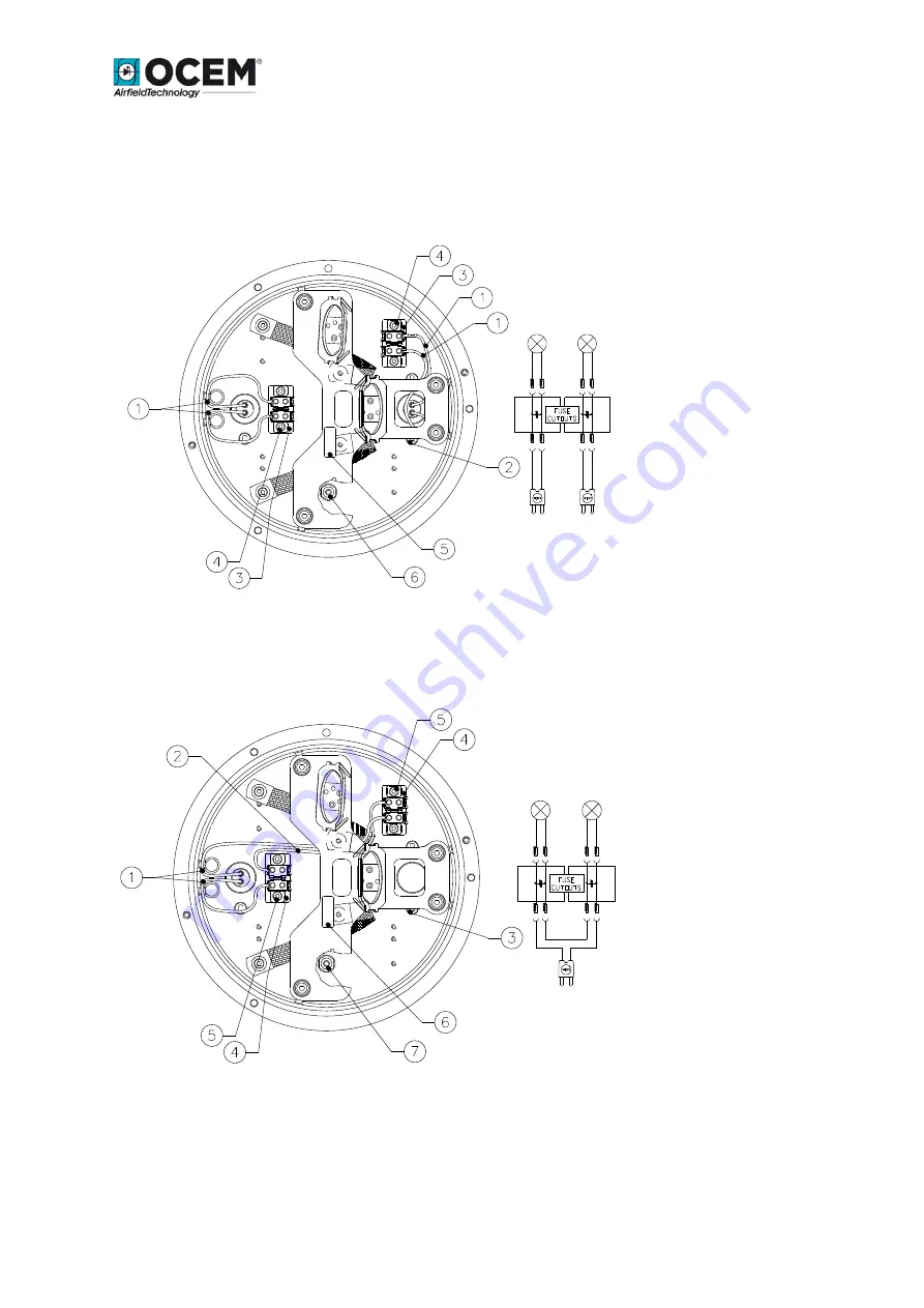
1 - 


Cable leads with plug 

2 - 


Letters "C" or "A and B" 
for cable leads 
identification 

3 - 


Insulating strips  

4 - 


Insulating strips 

fastening screws  

5 - 


Lamp supporting plate 

identification label 

6 - 


Leak test valve 


Figure 8 – Lower cover with two cable leads and optional fuse cutouts – Inside view 


1 - 


Cable lead with plug 

2 - 


Insulating strip-
insulating strip cable 

3 - 


Letters "C" or "A and B" 
for cable leads 
identification 

4 - 


Insulating strips  

5 - 


Insulating strips 

fastening screws  

6 - 


Lamp supporting plate 

identification label 

7 - 


Leak test valve 

Figure 9 – Lower cover with one cable lead and optional fuse cutout – Inside view 


Summary of Contents for SLRE Series

Page 1: ...DELIVERED BY MEANS OF THE AUTOMATIC KNOWLEDGE MANAGEMENT SYSTEM IT CAN BE SIGNED ON REQUEST THIS DOCUMENT AND THE DATA CONTAINED HERE IN IS PROPRIETARY PROPERTY AND SHALL NOT BE DUPLICATED USED OR DIS...

Page 2: ...applicable warranty period All costs of transportation of Products claimed not to be warranted and of those repaired or replaced to or from the facility of the Company shall be borne by Purchaser Com...

Page 3: ...unit opened the main circuit breaker and removed the supply to the unit by opening the circuit breaker switch on the distribution board at the beginning of the supply line Then wait discharge time at...

Page 4: ...SLRE INSTRUCTION MANUAL FOR USE INSTALLATION AND MAINTENANCE EDITIONS Date 13 10 2008 First issue 02 09 2010 04 30 2012 11 03 2014 New edition General revision New address of the Company General revis...

Page 5: ...ment Boring and Sawcutting 17 3 1 1 Scheme of Light Configuration 18 3 2 INSTALLING THE SHALLOW BASE 19 3 3 INSTALLING THE LIGHT UNIT ON L 868 BASE SIZE B 23 3 4 SECONDARY WIRING 24 4 MAINTENANCE 25 4...

Page 6: ...ibro non definito Figure 8 Lower cover with two cable leads and optional fuse cutouts Inside viewErrore Il segnalibro non definito Figure 9 Lower cover with one cable lead and optional fuse cutout Ins...

Page 7: ...0 2012 INSET RUNWAY EDGE LIGHT SLRE INSTRUCTION MANUAL FOR USE INSTALLATION AND MAINTENANCE Figure 25 Cable Lead With Plug 32 Figure 26 Vibration Damping Block 32 Figure 27 Lower Cover with Pressure V...

Page 8: ...t and roll over loads without damage The fixture can be bidirectional type bidirectional dome provided with two optical windows and equipped with two lamps that can operate simultaneously or in indepe...

Page 9: ...ount only one lamp one prism and one filter when required Fixtures can be provided with six kinds of lamp supporting plate in order to obtain the following configurations ICAO 45 m and 60 m C A P N 15...

Page 10: ...m long The plug is in compliance with FAA AC 150 5345 26 for very quick coupling with the receptacle mounted on the shallow base The fixture is 304 mm in diameter and 123 mm 18 5 mm for plugs high th...

Page 11: ...2 14 Vibration damping block 4 15 Spacer 4 16 HSCH M5x16 inox screw 4 17 5 inox grower washer 8 18 5 inox grower washer 5 19 O Ring 41150 silicone 1 20 O Ring 6850 silicone 1 22 HSCH M5x16 inox screw...

Page 12: ...Side Right Side C White R Red Y Yellow G Green X Screened Electrical System 1P One Cable Lead 2P Two Cable Leads Lamps 100 1x 10⁵ W 6 6A with reflector 200 2x 10⁵ W 6 6A with reflector Mounting Assem...

Page 13: ...2 Letter A not centered beam side 3 Slot for dome removal 4 Prisms 5 Through holes for light unit fastening 6 Label with arrow for toe in identification Figure 4 Dome C A Outside view 1 Letter C centr...

Page 14: ...ht unit fastening 4 Holes for lower cover fastening 5 Lower cover reference pin 6 Holes for mounting plate fastening 7 Holes for filter support fastening Figure 6 Dome C A Inside view 1 Window C to se...

Page 15: ...rips fastening screws 5 Lamp supporting plate identification label 6 Leak test valve Figure 8 Lower cover with two cable leads and optional fuse cutouts Inside view 1 Cable lead with plug 2 Insulating...
Page 16: ...able lead size 2 5 mm2 0 250 m long with female faston terminal for quick connection to the corresponding of the fixture An additional external grounding screw is provided close to the cable entry The...

Page 17: ...nections Inside the base two suitable holders Figure 10 n 9 are provided to properly sustain the secondary power cable in case of this cable is inside incoming through a conduit 3 INSTALLATION 3 1 Pav...

Page 18: ...htly concave to assure that the shallow base rest securely and in true position The recess can best be drilled using a diamond faced core drill in a sturdy stable drill rig Mark on the pavement surfac...

Page 19: ...E ELECTRICAL SYSTEM 3 Connect an insulated G Y grounding wire of suitable length to the grounding screw externally provided on the wall of the base 4 Splice the light base leads to the power cables us...

Page 20: ...he jig by operating the three leveling lobe knobs Figure 15 If necessary a weight may be placed on the jig to hold the light base in position The remainder of the space between the sides of the shallo...

Page 21: ...wire of the fixture with the receptacle and the grounding wire of the base press the fixture by hand onto the base and secure it using the six locking screws complete with washer one drop of screw pas...

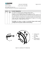
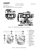
Page 22: ...00 150 150 Figure 14 12 shallow base for side or bottom ducts method B 1 Positioning jig 2 Align the jig notch with the mark on the pavement 3 Circular level 4 Screws and spacers for the jig mounting...

Page 23: ...sure the flange on the transformer housing is clean and the O Ring Figure 17 n 2 if used is in place in the O Ring groove Connect the plug of the fixture to the receptacle of the isolating transformer...

Page 24: ...vided with earthing connection the fixture secondary side is wired to the grounding network through the larger pin of fixture plug In case of an inset fixture installed in the taxiway runway pavement...

Page 25: ...fe the installed units should be subject to a maintenance program in accordance with the following instructions and taking as reference the Airport Service Manual ICAO Part 9 Airport Maintenance Pract...

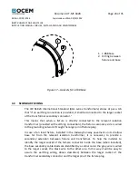
Page 26: ...T FROM THE BASE 4 2 1 Removing the fixture Remove the fixture from the base after switching off by unscrewing the six locking screws complete with washers Raise the fixture by using the two lifting to...

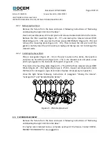
Page 27: ...kPa air pressure test This can be done by connecting an external air pressure line to the valve Figure 18 n 2 provided on the lower cover Immerge the assembly under water so air loss will be easily v...

Page 28: ...enever it is necessary remember the following rules Remove the fixture from the base and open it following instructions of Removing and Opening the Light Unit From the Base and proceed as follows remo...

Page 29: ...evant walls 4 4 2 Installing the New Prism Place a new gasket Figure 20 n 2 in the prism cavity on the dome then position and press by hand the prism Figure 20 n 3 in the relevant seat and place a new...

Page 30: ...ns of paragraph Closing the Fixture Leakage Test and Reinstalling the fixture 4 6 RELAMPING Remove the fixture from the base and open it following instructions of Removing and Opening the Light Unit F...

Page 31: ...stretched torn has a permanent set or some other defect which would prevent it from obtaining a water tight seal must be replaced with a new O Ring Remove the fixture from the base and open it followi...

Page 32: ...nsioned to allow the proper positioning when compressed between the mating surfaces Screws properly tightened are important in obtaining a complete seal TIGHTENING TORQUE lower cover HSCH M5x16 2 5 Nm...

Page 33: ...6 Place the gland gasket inside its seat and tighten the gland nut Restore internally the electrical connections Figure 25 Cable Lead With Plug Close the light fixture following instructions of parag...

Page 34: ...body to the lower cover from the inside of the fixture In case the pressure valve needs replacing operate as follows considering the fixture already opened following instructions of Removing and Openi...

Page 35: ...DGE LIGHT SLRE INSTRUCTION MANUAL FOR USE INSTALLATION AND MAINTENANCE 4 11 CLEANING Service life depends upon the entire assembly being waterproof All surfaces must be clean dry and free of all forei...

Reviews: