


28
Ocmis Irrigazione S.p.A. – INSTRUCTION AND WARNING MANUAL – Translation of Original Instructions
MUMR-R1.02 .EN - 31/07/2015
CHAPTER 3 - Description of the machine
Any modifi cation that alters the risks and/or functions of the machine, if it is carried out without the Manufacturer's authorisation, shall
forfeit any form of warranty, liability as well as its CE declaration of conformity.
CAUTION
The Manufacturer disclaims any liability in the event of damage to property or harm to persons should the product be misused.
NOTE
It is the buyer's unequivocal responsibility to carry out a product inspection upon receipt of the product and to ensure the supply
matches the order specifi cations.
Immediately inform the Manufacturer in the event of any non conformity.
Also ensure there has been no damage during transport.
Should any damage due to shipping be observed, in order not to forfeit the contractual warranty, we recommend immediately stopping any installation
operation and use of the machine. Send a written complaint to the Manufacturer, documented with photographs of the damaged parts, within and not
later than 15 days after the product's date of delivery.
Also, ensure the packaging contains all the optional features you have ordered and all standard supplied components.
3.3
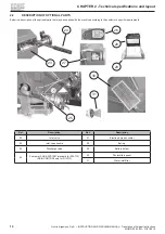
MACHINE DESCRIPTION
The machine has been designed to irrigate large agricultural surfaces with raingun or spray booms.
It is normally used in farming for growing various types of crops.
The essential concept is to irrigate wide surfaces without the physical need for personnel to manually move the water hoses from one area of the site
to be irrigated to the next, since the hose is unwound and reeled back in by the suitably designed automations provided.
The solution has stemmed from the use of a semi-hard polyethylene hose which has made it possible to wind it onto a spindle (reel).
The hose is unwound on the soil to be irrigated by towing the raingun trolley with the tractor only after the hose reel travelling raingun has been
properly positioned. The hose is then reeled back in mechanically.
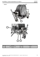
Once the raingun trolley has been properly positioned on the surface to be irrigated, the operating logic entails conveying the pressurised water to the
water inlet of the machine, which, by effect of the liquid's intrinsic force, actuates the turbine impeller located on the speed gearbox input shaft, and
which, in turn, rotates the reel around which the polyethylene hose is wound.
The hose has one end fastened to the reel's rotating centre shaft and the other end is normally connected to a wheeled trolley that supports the
equipment (raingun) through which the liquid irrigates the surface of the site.
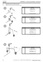
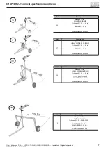
The structure the machine consists of is placed on a two or four-wheel traveller which may be towed by a tractor to adequately move it to the various
work positions. It is also equipped with independent actuators (manual or mechanical) to adjust orientation and assure its stability in operation.
A signifi cant feature is the automatic hose reeling stop at the end of the work run. When the hose has completely been reeled in and the raingun trolley
reaches its end position, a specifi c mechanical lever system interrupts the reel's rotation.
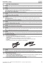
Guards and protection devices have been provided to prevent
contact with moving mechanical parts, in order to meet the provisions of applicable regulations for the type of machine.
The surfaces of the metal structure, including the traveller and the raingun trolley, are heat treated by hot dip galvanising for durability over time, thus
preventing oxidation due to contact with the liquid that is sprayed and/or to exposure to the weather.
To identify which of these machines is the one most suited to the specifi c use, calculate how many square metres need to be irrigated, the fl ow rate,
the length of the hose, after which the hose diameter is identifi ed, as is the size of the machine to be used, as set out in this manual.
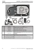
In order to make functional utilisation easier, a range of optional accessories is available, such as:
•
computer;
•
inlet valve;
•
discharge valve;
•
and so on.
Please refer to chapter 2 for further details and descriptions of the optional accessories that may be supplied with the machine.
Summary of Contents for MR
Page 99: ......


