


59
Ocmis Irrigazione S.p.A. – INSTRUCTION AND WARNING MANUAL – Translation of Original Instructions
MUMR-R1.02 .EN - 31/07/2015
CHAPTER 6 - Use and Operation
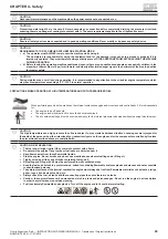
CAUTION: HYDRAULIC OIL LEVEL CHECK
Do not add oil beyond the maximum level. This might damage the hydraulic components and cause oil to seep out. Do not add
oils other than the recommended ones.
4. Check the following components to ascertain any damage or loosened or missing parts:
- pipes, fi ttings and cylinders of the oil hydraulic system;
- pipes, fi ttings and valves of the irrigation water system;
- nuts, bolts and other fastening devices (see tightening torques paragraph 7.4.2.7);
- electrical components, wiring and electrical cables.
5. Check the entire machine to identify any:
- damage or detached parts;
- cracking of welds or structural components.
6. Ensure all the casings and guards are intact and correctly locked in their housings.
7. Check the electrical system if the machine is equipped with it.
8. Check the battery status if the machine is equipped with it, namely:
- proper fastening of + / - terminals;
- electrical charge;
- electrolytic liquid level.
6.2.2
FUNCTIONAL TESTS WITH REELED IN HOSE AND MACHINE STATIONARY
It is the operator's responsibility to perform functional tests.
The purpose of the functional tests is to uncover any malfunction before the machine is started up. The operator must follow the instructions step by
step in order to test all the machine's functions.
A damaged machine must never be used. Should any damage or change be detected with respect to the initial standard conditions, the machine must
be marked out and put out of service for the required repairs.
When the repairs have been performed, the operator must again perform a preoperative inspection and must perform functional tests prior to using
the machine.
Please refer to the following list and check each listed element and/or part.
6.2.2.1
TESTS ON MANUAL AND/OR OIL HYDRAULIC ACTUATIONS FOR MACHINE PLACEMENT FUNCTIONS
Prior to performing the movements listed below, the responsible Operator must ensure that:
•
The ground on which the machine is to be placed is level, not on a slope and adequately fi rm.
•
There are no persons, animals or property in the manoeuvre area in front of the machine.
1) MANUALLY ACTUATED FRONT STABILISER LEG
For MR-MR/1 Lift the tow bar so its lower part is able to be anchored to the ground (see ref. 6 par.2.1) and hook the chain onto the frame.
For MRR-R1AT15 With a suitable hand crank at the top of the front stabiliser leg (see ref. 7 par.2.1).
Rotate clockwise to lower the bottom plate to the ground.
2) MANUAL REEL ROTATION ON THE VERTICAL AXIS (only for
MRR-R1AT15
)
Prior to performing this movement, ensure the machine is on even ground and not on a slope. This is to avoid a change in masses from causing
sudden partial rotation. Should you wish to manually rotate it on minimally sloping ground, another person is needed to manually help the operator
in supporting the reel, for the rotation to be controlled. If the operating ground where the machine is to be used is sloping (not over 8.5°), it is
recommended to orient the reel directly with the traveller hooked on the tractor.
In proper planarity conditions, remove the locking pin on the traveller (see ref. 21 par. 2.1) and push by hand to reach the desired position, then insert
the locking pin again in the closest seat to the working position.
3) MANUALLY OR MECHANICALLY ACTUATED REAR ANCHOR STABILISERS
For MR-MR/1-MRR Release the rear stabilisers chains and drive them into the ground (see ref. 13 par. 2.1).
For R1AT15 (options for MRR) Lower the rear stabilisers to the ground by means of their crank handles (see ref. 13 par. 2.1).
6.2.2.2
TESTS ON OPERATION CONTROLS WITH MACHINE STATIONARY
1) LEVER TEST ON THE TURBO-GEARBOX FOR MANUALLY ENGAGING/RELEASING TRACTION
CAUTION:
Prior to operating the traction engaging lever, set the turbine RPM to the minimum with the manual by-pass lever or with the
computer.
Move the lever (see ref. 47 par2.5.1) to the WORK positions and ensure it has engaged correctly.
Insert the handwheel (see ref. 48 par. 2.5.1) in the power take off located on the turbo-gearbox and with the lever in the WORK position ensure the
hose is reeled on when it is rotated anti-clockwise.
2) TEST AUTOMATIC TRACTION DISENGAGEMENT PRIOR TO: CONNECTING THE TROLLEY TO THE HOSE AND/OR UNWINDING THE
HOSE
Premise: all adjustments for proper operation of the machines are carried out in the factory in the testing stage, however in order to be more confi dent
that no tampering or either voluntary or accidental movements have occurred during transport, it is recommended to perform some checks as follows:
Summary of Contents for MR
Page 99: ......


