


61
Ocmis Irrigazione S.p.A. – INSTRUCTION AND WARNING MANUAL – Translation of Original Instructions
MUMR-R1.02 .EN - 31/07/2015
CHAPTER 6 - Use and Operation
3) TEST ON MACHINE STOP FOR RAINGUN TROLLEY STROKE END AND RELEVANT HITCHING FOR LOADING THE SAME ON TO THE
SUPPORT FRAME
Premise: the adjustments have been performed in the factory during testing, except those under items 1 - 2 on the following page which are to be
performed after connecting the raingun trolley to the polyethylene hose wound on the machine's reel, and in any case after anchoring the rear of the
machine to the ground (as shown under item 3 on the following page).
Procedure to be followed for connecting the raingun trolley to the machine, the stop bracket to the hose and for performing the relevant adjustments
as shown in the following pictures:
•
Lower the rear stabilisers so they are properly anchored to the ground (as indicated in item 3 on the following page). Refer to paragraph 6.2.2.1
(item 3) to perform this operation.
•
For MR/1- MRR - R1AT15 lower the trolley support frame.
•
Pull the lever (see ref. 49 par.2.5.1) so that the ratchet is free from the crown gear teeth. To aid this operation, insert the handwheel in the PTO
of the gearbox and turn the reel clockwise.
•
Move the lever (see ref. 47 par.2.5.1) into the 0 position (STOP) and simultaneously pull the hose, unwinding 3 - 4 metres.
•
Use the handwheel (see ref. 48 par.2.5.1) to rotate clockwise and unwind 3 - 4 metres of hose, in order to connect the trolley outside its lifting area.
•
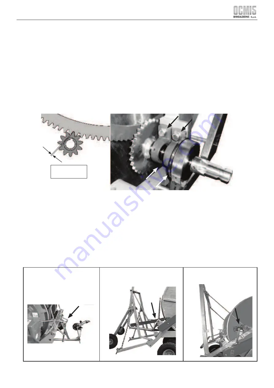
While unwinding the hose, ensure the pinion located on the gearbox output shaft meshes properly with the gear on the side of the reel (maximum
clearance tolerance between 1÷ 2 mm / 0.4 ÷ 0.8 in.).
•
To adjust the clearance, loosen the 4 fi xing screws on the 2 supports and then slightly move to the side to achieve optimal unwinding position.
1 ÷ 2 mm.
0.04 ÷ 0.08 in.
•
Connect the hose to the trolley.
•
Use the handwheel (see ref. 48 par. 2.5.1) turn anti-clockwise to reel the hose back in and move the trolley closer to the machine up to the optimal
position for hitching to the frame (as shown under item 2).
•
Place the stop bracket on the hose (as shown under item 1).
•
Lay the upper part of the bracket to the lower rod of the corrector, complying with condition b) set out above.
•
(Lock the stop bracket on the hose with the relevant screws only for trolleys ref. 41 and 42 par. 2.3.1). Mount the raingun on the trolley.
•
Caution: for safety reasons only the use of slow return rainguns is allowed, with speed not exceeding 1 RAD-S-1.
•
Adjust the height of the raingun trolley so that: for Skid trolleys (see ref.36,37,38 and ref.39 par. 2.3.1), the skid is placed evenly on the ground; for
3-Wheel or Side Unwinding trolleys (see ref.40 - 41 and ref. 42 par. 2.3.1), the base of the raingun operates horizontally.
•
Upon completing these operations, the trolley may be lifted from the ground, by proceeding as follows:
•
For MR Manually lift the trolley using the suitable handle and hook it to the machine
•
For MR/1 - MRR Manually lift the trolley and hook the suitable lever to the machine.
•
For R1AT15 Turn the crank handle located on the winch so that the loading frame lifts the trolley.
MR
MR/1 - MRR
R1AT15
Summary of Contents for MR
Page 99: ......


