


80
Ocmis Irrigazione S.p.A. – INSTRUCTION AND WARNING MANUAL – Translation of Original Instructions
MUMR-R1.02 .EN - 31/07/2015
CHAPTER 7 - Maintenance
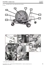
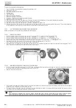
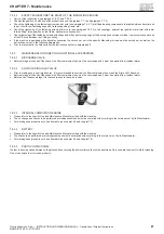
Removal of the wheels
The wheels may only be replaced by qualifi ed and authorised technical personnel.
•
Handle all parts with the utmost care.
•
Do not place your hands, fi ngers and limbs between parts.
•
Wear safety clothing and approved PPE such as goggles, gloves and safety shoes.
•
Ensure the tyre is completely defl ated before starting removal.
•
Place the machine on a fl at surface and block it with the parking brake.
•
Place wedges under the wheels that remain in contact with the ground.
Before proceeding with any subsequent operation, completely defl ate the tyre, also removing the middle body of the valve for more complete and
safer air removal.
With the wheel to be replaced still in contact with the ground, partially loosen its fi xing screws or nuts.
Then lift the machine until the wheel is suffi ciently detached from the ground and secure the trolley by placing it on adequate and stable supports.
Proceed with full removal of the wheel's screws or nuts and extract it from the hub.
7.4.2.6
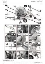
WHEEL RIMS
Fitting the rims
Upon fi tting check integrity and conformity of the components used:
•
Do not use or repair damaged or warped wheels.
•
Do not repair rims or discs by welding.
•
Replace faulty elements with others of the same type, profi le and size.
•
Clean all coupling surfaces and protect them from rust.
•
Use a rubber mallet to assemble the parts.
•
Spread a solution of soap in water or specifi c grease for tyre fi tting on the rim groove and on the base of the tyre.
•
Never use petroleum based lubricants or antifreeze.
•
Ensure the rim is of suitable size for the wheel.
•
Lubricate the parts of the wheel in contact with the heel and the inner tube.
Removing rims from the wheels
Prior to starting disassembly of a wheel of the vehicle, ensure the tyre is completely removed and ensure the tyre casing and/or rim are not damaged.
•
Remove the nuts fastening the two parts of the rim.
•
Loosen the heel of the tyre from the side fl ange.
•
Remove the rim from the wheel.
•
Remove the inner tube.
7.4.2.7
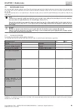
SCREW TIGHTENING TORQUES
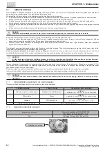
During maintenance procedures it is often required to tighten steel screws of varying types and sizes with a torque wrench.
The following tables show the maximum tightening torque to be used according to the resistance of the material and screw size.
TIGHTENING TORQUES FOR STEEL SCREWS WITH ISO THREAD
Maximum tightening torques for metric screws with friction coeffi cient 0.14
Ø
SCREW
HEXAGON
new
►
6.8
8.8
10.9
12.9
old
►
6S
8G
10K
12K
ø screw
hexagon
Pitch
Pitch
Pitch
Pitch
Pitch
coarse
fi ne
coarse
fi ne
coarse
fi ne
coarse
fi ne
coarse
fi ne
mm
mm
mm
Nm
Nm
Nm
Nm
Nm
Nm
Nm
Nm
M6
10
1
-
7.8
-
10
-
15
-
18
-
M8
13
1.25
1
19
20
25
27
35
38
42
46
M10
17
1.5
1.25
37
39
50
53
70
74
84
89
M12
19
1.75
1.5
36
67
85
89
119
125
143
150
M14
22
2
1.5
101
111
135
148
190
208
228
250
M16
24
2
1.5
159
170
212
226
298
318
357
382
M18
27
2.5
2
218
233
290
310
402
436
490
523
M20
30
2.5
2
310
327
413
436
580
614
697
736
M22
34
2.5
2
426
448
568
597
798
840
958
1008
M24
36
3
2
535
586
714
781
1004
1098
1204
1317
M27
41
3
2
788
855
1050
1139
1477
1602
1772
1923
M30
46
4
2
1072
1193
1429
1590
2009
2236
2411
2648
M33
50
3.5
2
1456
1602
1941
2136
2729
3004
3275
3605
M36
55
4
3
1873
1989
2497
2652
3511
3730
4213
4476
M39
60
4
3
2431
2573
3242
3430
4559
4824
5471
5789
- The torque settings shown in the table correspond to 80% of the yield point
- For self-locking nuts or ring nuts the torque setting shall be increased by 15% .
- The settings shown are indicative
Summary of Contents for MR
Page 99: ......


