background image

2575D Fluid Pan & Tilt Head

3

Preface

Thank you and congratulations on the purchase of your new 2575D from OConnor.

We want you to get the most from your new 2575D, and therefore encourage you to read this 
operator's guide to familiarize yourself with its many features, some of which may be new to you. 
It also covers essential health and safety information and a section on maintenance that will 
ensure you keep your new product in perfect condition.

Please register your purchase online at www.ocon.com.

Features and benefits of your new 2575D

The 2575D head is the flagship of OConnor's ultimate range of fluid heads and features 
OConnor's stepless counterbalance system as well as ultra-smooth pan and tilt fluid drag 
designed for cine style shooting.

A collapsible counterbalance crank handle and numerical readout make counterbalancing the 
payload easy. The new platform has all the controls on the camera operator's side of the head 
(left side) and features a platform scale on both sides and four rosette handle mountings. The 
platform release lever has a one touch finger actuated safety release catch-while still requiring 
conscious effort.

OConnor's fluid drag system allows an extremely quick pan movement from one position to 
another, recovering instantly without any spring back.

You can set up easily in low light conditions using the illuminated bubble level.

Summary of Contents for 2575D

Page 1: ...2575D Pan Tilt Head Fluid C1234 0001 C1234 0002 C1234 0003 C1234 0004 C1234 0005 C1234 0006 ONLINE R EGISTR ATION Operators Guide H C1234 4980 4 TTP R EGISTR ATION OCON COM ...

Page 2: ...OConnor 2575D Fluid Pan Tilt Head Operators Guide Publication Part No C1234 4980 Issue 4 ...

Page 3: ...ent and permission in writing of Vitec Group plc Trademarks OConnor is a registered trademark of the Vitec Group plc Important information about this document Information contained within this document is subject to change Vitec Videocom Limited reserves the right without notice to make changes in equipment design or performance as progress in engineering manufacturing or technology may warrant Pu...

Page 4: ...r s ultimate range of fluid heads and features OConnor s stepless counterbalance system as well as ultra smooth pan and tilt fluid drag designed for cine style shooting A collapsible counterbalance crank handle and numerical readout make counterbalancing the payload easy The new platform has all the controls on the camera operator s side of the head left side and features a platform scale on both ...

Page 5: ... product must not be treated as household waste By ensuring these batteries are disposed of correctly you will help prevent potentially negative consequences for the environment and human health and help conserve natural resources Read the Battery Replacement section in this manual for instructions on how to remove the battery from the product safely Hand the battery over to the applicable collect...

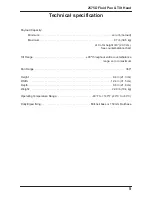
Page 6: ... height of 8 20 3 cm See counterbalance chart Tilt Range 90º throughout entire counterbalance range zero to maximum Pan Range 360 Height 8 4 in 21 3 cm Width 12 4 in 31 5 cm Depth 8 6 in 21 8 cm Weight 22 9 lb 10 4 kg Operating Temperature Range 40 F to 140 F 40 C to 60 C Dolly tripod fixing Mitchell base or 150 mm Ball base ...

Page 7: ...Operators Guide 6 ...

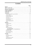
Page 8: ...Locks 11 Tilt Lock Pin 11 Illuminated Bubble Level 11 Handle Mounting 11 Camera Mounting Platform 11 Bases 12 Operation 13 Installing the head 13 Handles 13 Mounting a camera 13 Stability 14 Balancing the Head 14 Fore and Aft Balance 15 Payload Weight and C of G Height Adjustment 16 Locking the Platform 16 Pan and Tilt Locks 17 Pan and Tilt Fluid Drag 17 Storing the head 17 Servicing 18 General 18...

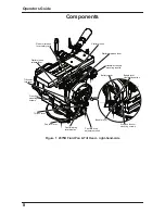
Page 9: ...b Pan fluid drag level display Pan lock lever Tilt lock lever Front box mounting screws Tilt center lock lever Platform hook release lever Platform release lever safety catch Platform hook Handle accessory mounting rosette Platform release lever Bubble level illumination button Eyepiece leveller mounting screws Bubble level ...

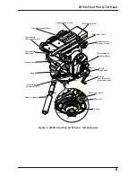
Page 10: ...e scale Handle accessory mounting rosette Counterbalance numerical display Tilt fluid drag display Folding counterbalance adjustment crank Mitchell key marker Mitchell key Tie down Camera plate clamp release lever Camera plate clamp lever Tilt fluid drag adjustment knob Camera mounting plate Handle clamp Handle Handle extension ...

Page 11: ...counterbalance and the head can still be tilted 90º Numeric Display The numeric display indicates the setting of the counterbalance mechanism on a scale of 0 99 Adjust the counterbalance crank clockwise to increase the counterbalance setting and counter clockwise to reduce it The display has a three color coded band offering advance warning of cranking to the end limits Green represents the normal...

Page 12: ... left side of the head can be illuminated by pressing the bubble level illumination button The light will go out after approximately 20 seconds Handle Mounting Handle mounting rosettes are located at the front and rear of the head on both the left and right sides A telescoping extension handle is supplied and is attached using the handle clamp with angular adjustment available on the rosette serra...

Page 13: ...rs Guide 12 Bases The 2575D head can be fitted with either a Mitchell base and tie down or a 150 mm ball base and tie down Bases are secured by four 20 socket head cap screws requiring a 3 16 hex drive wrench ...

Page 14: ...e platform towards the right side of the head until a loud click is heard Once the platform hook engages the camera mounting plate the camera is captive but not locked 5 Alternatively press down and hold the red platform hook release lever on the front left hand side of the head and position the camera mounting plate on top of the head Release the red hook release lever until the platform hook aut...

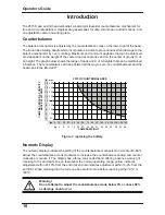
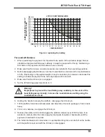
Page 15: ...e camera Second once balanced the head and its payload can be set to any tilt position and the head will maintain this position with hands off The chart below shows the range of load and C of G heights that can be maintained in balance The area under the balance curve colored white corresponds to load C of G combinations that can be balanced over the full tilt range of 90 The area above the balanc...

Page 16: ...tilt lock pin 7 Tilt the platform forwards and backwards and determine if camera package is front or back heavy 8 If it is not in balance re engage the tilt lock pin 9 Release the safety catch and disengage the platform release lever With the help of an assistant carefully slide the camera payload and plate forwards or backwards until the payload is balanced fore and aft 10 The horizontal balance ...

Page 17: ...andle and turn it clockwise to increase or counter clockwise to decrease the counterbalance setting as required 4 Using the handle tilt the platform upward and downward to recheck the balance Readjust counterbalance until balance is achieved 5 Make a note of the final numeric counterbalance setting to simplify rebalancing this particular payload 6 When the payload weight and C of G height adjustme...

Page 18: ...and Tilt Fluid Drag Both the pan and tilt mechanisms incorporate the OConnor ultra smooth fluid drag system to ensure smooth movement The pan drag adjustment knob is located on the lower right rear of the head and the tilt drag adjustment knob on the lower left of the head Both controls are continuously adjustable from 0 to 9 To increase drag turn the knob clockwise towards a higher setting To dec...

Page 19: ...that accumulates during storage or periods of non use may be removed with a semi stiff brush Particular attention should be paid to the dovetail faces of the camera mounting area Use out of doors under adverse conditions may require special attention and the head should be covered when not in use Salt spray should be washed off using fresh water at the earliest opportunity Sand and dirt act as an ...

Page 20: ...rew the battery cover 3 Carefully pull the battery out of its compartment with its ribbon 4 Fit a replacement CR 2032 3v battery in the compartment ensuring that the positive side of the battery faces outermost and the ribbon is correctly positioned 5 Replace the battery cover and tighten using a coin or flat blade screwdriver 6 Press the bubble level illumination button and verify that the bubble...

Page 21: ...Operators Guide 20 NOTES ...

Page 22: ...Specifications are subject to change without notice www ocon com sales ocon com oconnor A Vitec Group brand ...

Reviews: