


3.7 Belt Tensioner Replacement
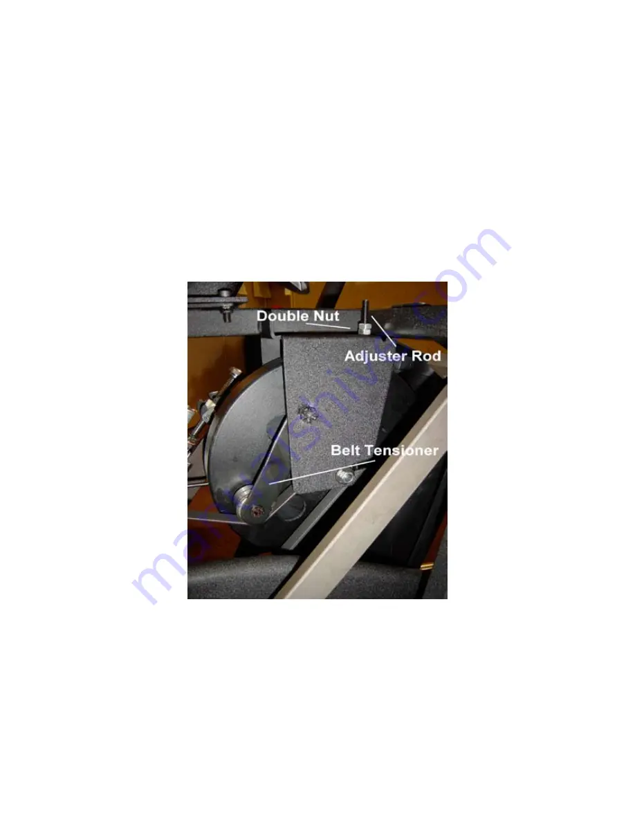
1. Unplug the unit and remove the shrouds to access the inside. Figure 3.13 shows the belt tensioner assembly.
2. Use a 13mm wrench to remove the double nut and the adjuster rod.
3. Remove the nylock nut that holds the belt tensioner to the frame.
4. Remove the belt tensioner and replace it with a new one.
5. Tighten the nylock nut that holds the belt tensioner to the frame.
6. Tighten the double nut on the adjuster rod.
7. Twist the drive belt with your fingers. It should move approximately 90º. Adjust as necessary so that slippage does
not occur between the belt and the pulley while pedaling the unit and when changing direction while pedaling.
Figure 3.13
Q45 3.7
Summary of Contents for Q45
Page 1: ...Q45 Q45e Q45ce ...
Page 2: ......
Page 4: ......
Page 5: ...Notes ...
Page 6: ...Figure 1 1 Figure 1 3 Right Clevis Notice step orientation to outside of machine Figure 1 2 ...
Page 8: ...Q45 1 2 Figure 1 4 ...
Page 12: ...Figure 2 2 Figure 2 3 Figure 2 1 Q45 2 1 ...
Page 14: ...Figure 2 5 Q45 2 2 Figure 2 6 ...
Page 16: ...Figure 2 7 Q45 2 2 Figure 2 8 Nylock nut Clevis bushing Figure 2 9 ...
Page 18: ...Q45 2 2 Figure 2 11 Figure 2 12 Figure 2 10 ...
Page 20: ...Q45 2 2 Figure 2 13 Figure 2 14 Figure 2 16 Figure 2 15 ...
Page 22: ...Q45 2 2 Figure 2 20 Figure 2 19 Figure 2 17 Figure 2 18 ...
Page 24: ...Figure 2 22 Q45 2 3 Figure 2 21 Speed Speed Sensors Sensors ...
Page 26: ...Q45 2 3 Figure 2 27 Figure 2 25 Figure 2 23 Figure 2 24 ...
Page 28: ...Figure 2 28 Figure 2 27 Figure 2 29 ...
Page 30: ...Figure 2 30 Figure 2 32 Figure 2 31 ...
Page 38: ...Q45 2 5 Figure 2 41 ...
Page 40: ...Q45 2 5 Figure 2 42 ...
Page 42: ...Q45 3 1 Figure 3 1 ...
Page 44: ...Q45 3 1 Notes ...
Page 46: ...Q45 3 2 Notes ...
Page 48: ...Figure 3 7 Q45 3 4 Figure 3 6 Stability Link 18mm Bolt ...
Page 54: ...Q45 3 6 Notes ...
Page 56: ...Q45 3 8 Figure 3 14 Figure 3 15 ...
Page 58: ...Figure 3 16 Figure 3 17 Figure 3 18 Q45 3 9 ...
Page 60: ...Q45 3 9 Notes ...
Page 62: ...Q45 3 11 Figure 3 21 Figure 3 20 Figure 3 22 Older units Newer units ...
Page 64: ...Q45 3 12 Figure 3 24 Figure 3 23 ...
Page 66: ...Figure 3 26 Figure 3 25 Speed Sensors Q45 3 13 ...
Page 68: ...Notes Q45 3 13 ...
Page 70: ...Q45 3 15 Figure 3 29 Figure 3 28 ...
Page 72: ...Q45 3 15 Notes ...
Page 74: ...Q45 3 17 Figure 3 31 Figure 3 32 Figure 3 33 ...
Page 76: ...Q45 3 18 Figure 3 34 Figure 3 35 Figure 3 36 ...
Page 78: ...Q45 3 19 Figure 3 37 Figure 3 38 ...
Page 80: ...Q45 3 20 Figure 3 39 Figure 3 41 Figure 3 40 ...
Page 82: ......


