110507-001 REV D Page 2/2
USA & Canada
888-OCTANE4
Latin America/Asian Pacific
001-763-757-2662
Europe/Middle East/Africa
31-10-2662412
Questions?
octanefitness.com
©2015 Octane Fitness. All rights reserved.
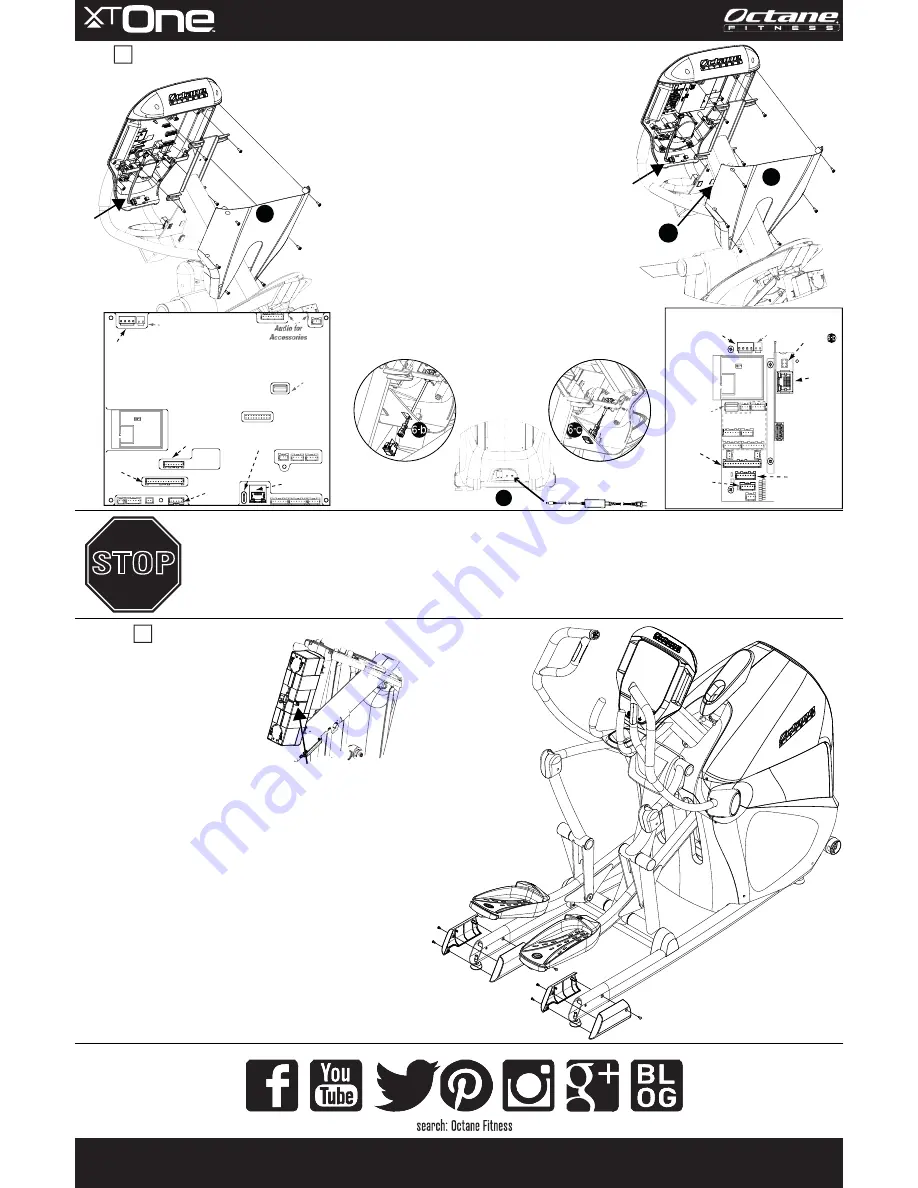
Assembly Instructions
Connect cable on battery to cable in base (if you have not already done so
during installation of PVS or 900MHz accessory).
Verify power to console and, if applicable, complete Console Setup
according to instructions found in
the console guide and Setup Instructions
(Part Number 110506-001 – Standard Console or Part Number 110600-001 –
Smart Console).
Use a #2 Phillips srewdriver to attach back cover to console
with C-1 (quantity 6); tighten (shown in Section D illustration).
Attach one left and one right frame end cover around each frame end with
B-3 screws (quantity 3 each). Tighten with #2 Phillips screwdriver.
Position and re-install top shroud using 4 screws retained in Step A-1 (not shown).
Wrap mast boot around base of mast.
Level machine; adjust and lock levelers.
E
Connect Battery,
Attach Covers &
Mast Boot,
Level Machine
D
Install Console
Separate console back from console front;
set console back aside (not shown).
Connect the C-SAFE cable from the C-SAFE port on the mast
to the console (cable not shown).
Note:
If you are installing a
900 MHz accessory, remove and discard the C-SAFE cable.
Connect heart rate cable attached to heart rate
board on console back to heart rate cable from mast
(black, 6-pin connector).
Make additional cable connections from mast to back of console:
Standard Console:
power,
handlebars,
base,
LAN,
ground
Smart Console:
power,
handlebars,
base,
LAN
(leave ground unconnected)
Using Phillips #2 screwdriver, attach console front to
top of mast with C-1 (quantity 4); tighten.
For Smart console only:
Install power switch; connect cable and
power.
a. Remove plug from mast plate.
b. Connect cable to console board. Route other end through the
opening where plug was removed. Connect cable to switch.
c. Press switch into opening until flush with bottom of mast plate.
d. Connect power cord and power supply. Plug into base of unit and
wall socket. Press power switch to power on the console (not shown).
If you have the optional
Personal Viewing System (PVS) accessory
, refer to
Personal Viewing System (PVS) Assembly Instructions
(Part Number 110748-001), located in the box with your PVS accessory, then return to these instructions to complete final assembly.
If you have the optional
900 MHz accessory
, refer to
900 MHz Assembly Instructions
(Part Number 110749-001),
located in the box with your 900 MHz accessory, then return to these instructions to complete final assembly.
STOP
Standard Console
Smart Console
Console to Base
(white, 14-pin)
Handlebar Control
(white, 6-pin)
Console Ground
(metal; green wire from mast)
Reserved
(unused)
(unused)
Power
(white, 4-pin)
Power for
Accessories
(unused)
Reserved for
Software Field Update
(black)
LAN
(RS-232)
C-SAFE
(Connect from mast
in Step
)
Standard Console
6-a
-
Console to Base
(white, 14-pin)
Handlebar Control
(white, 6-pin)
Smart Console
Power
(white, 4-pin)
Power for
Accessories
(unused)
(unused)
Reserved for
Software Field Update
(black)
Software Field Update
C-SAFE
(Connect from mast
in Step
)
Reserved
(unused)
ON/OFF Switch
(connect in Step
)
LAN
(RS-232)
6-d
(Install back cover)
E-3
(Install back cover)
E-3


