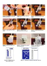
Figure 1 – the switches with clips
and wiring harness
Figure 2 – removing the extruder
nozzle cover
Figure 3 - cover removed to reveal
cables
Figure 4 - removing the extruder
cable
Figure 5 - extruder cable
disconnected from its header
Figure 6 – Octave switch harness
connected
Figure 7 – Extruder nozzle cover
replaced
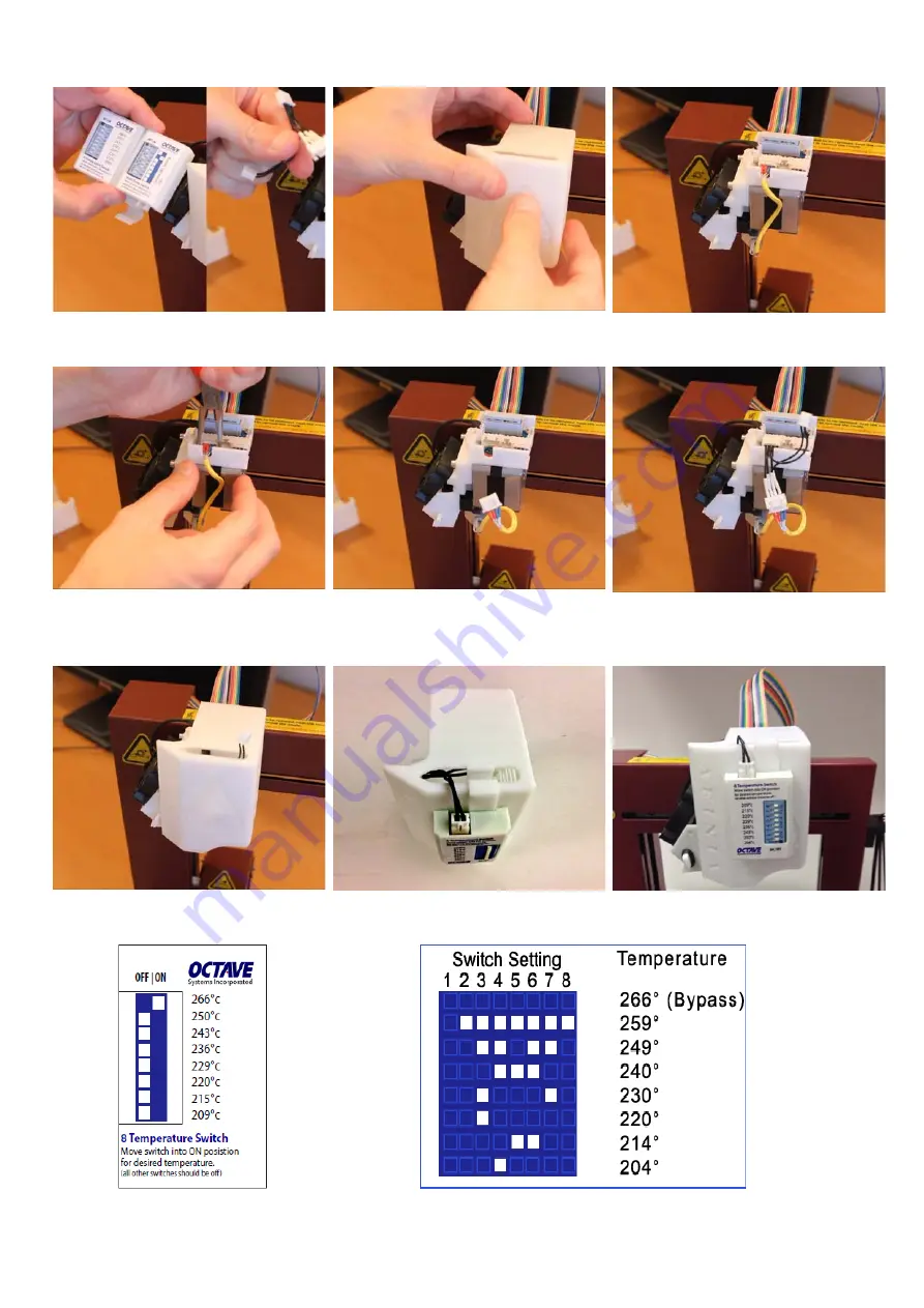
Figure 8 - The temperature switch
mounting position
Figure 9 - The temperature switch
installed on the printer
Figure 10 - Settings for the 8
Temperature Switch
Figure 11 – Settings for the Multi Temperature Switches