background image


11


3. GETTING STARTED 


3.4. Switching on for the first time – the Soft-Start feature 


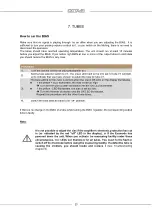
The  MRE  220  SE  is  equipped  with  a  multi-stage  Soft-Start-Turn-On  safety  circuit  which  extends 
component as well as tube life considerably by protecting against stress caused by typical high inrush 
currents during switch on. 


Procedure


1. 

Connect the MRE 220 SE to the mains. 
 

2. 

Switch on the MRE 220 SE using the amplifier’s mains power on/off switch (see chapter 
4 front panel 

).The Power-LED 

 will illuminate. 


3. 

Turn the Input Rotary Selector 


to Muting – the Muting LED 

goes out 


4. 

Turn the Function Rotary Selector 

to Eco off – the Ecomode LED on the top side goes 

out (see chapter 6.4 Ecomode). 
 

5. 

After approx. 60 seconds you hear a relay click noise. The soft start phase is finished 
and the power tubes start to work 


3.5. Checking the power tubes – setting the BIAS 
 

For the first function check you don’t have to connect the loudspeakers or the preamp.  
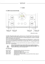
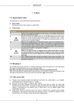
The trim pots to adjust the BIAS are located next to their respective tubes. Next to each trim pot you 
will see a pilot lamp, which shows which tubes have been selected with the bias selector switch. A 
row of LEDs in front of the transformer cover assists you in setting the bias correctly. It shows three 
conditions: bias too low -, correct ok, and too high +. Additional you find two LED’s indicating the 
status of the ECO Mode Chap 6.5.) and the protection circuit (chap 6.3.).


Before checking the BIAS please wait five to ten minutes. 

Because the tubes are still cold you 

would adjust the wrong BIAS. 


Summary of Contents for MRE 220 SE

Page 1: ...MRE 220 SE Owner s Manual English...

Page 2: ...insights into the interaction of amplifier and loudspeaker With tube amplifiers in particular a general reluctance to depart from the classic circuit designs has not done the technology any favors Al...

Page 3: ...4...
Page 4: ...selector alternative power tubes 16 6 2 Soft Start Inrush current limitation 16 6 3 Electronic Protection System 17 6 4 Muting function 17 6 5 Ecomode power saving mode 18 6 6 Setting of the damping f...

Page 5: ...ith this absolutely unique adjustment option within the power amplifier the interaction of the MRE 220 SE with speakers can be optimized almost perfectly The MRE 220 SE therefore has a switch with whi...

Page 6: ...rue balanced XLR inputs with a very high common mode rejection ratio that eliminates unwanted hum and high frequency distortion induced in the small signal connection to the preamp Power Management Th...

Page 7: ...et an engineer to replace blown fuses with ones of the same type and rating If your amplifier requires servicing please ship or take your equipment directly to OCTAVE or to one of our authorized servi...

Page 8: ...terials gases or vapors Avoid areas where there may be heavy accumulations of dust or where the unit may be subject to mechanical vibration Place your OCTAVE amplifier on a stable level surface 2 Gril...

Page 9: ...thout its protective grille is dangerous and not recommended Procedure 1 For your own safety switch the amplifier off using the on off switch 2 Pull the grille upward to remove 3 3 Installing the powe...

Page 10: ...4 Ecomode 5 After approx 60 seconds you hear a relay click noise The soft start phase is finished and the power tubes start to work 3 5 Checking the power tubes setting the BIAS For the first functio...

Page 11: ...ively the warm up period the BIAS control LEDs will change from yellow to green in case the BIAS Measurement Electronic is switched to tube 1 for example This indicates the correct BIAS Check all four...

Page 12: ...e if the ECO turns down the unit after 8 10 minutes Eco Off The Ecomode facility is disabled and simultaneously the BIAS measure ment facility is Off Position V1 V4 The BIAS measurement facility is co...

Page 13: ...ted is 0 ohms and for Disconnected is 18 ohms Loudspeaker Terminal Binding posts to connect the speaker cable Red positive terminal Black negative terminal You can connect either 4 mm Banana connector...

Page 14: ...ate Model and Serial Number Mains supply receptacle IEC socket with integrated fuse holder The fuse is located in a pullout compartment above the socket You can open the fuse compartment after removin...

Page 15: ...switching the Power Selector turn OFF the mains rocker switch After switching from power LOW to HIGH and vice versa the BIAS should be corrected in case of using the same output tubes Normally there...

Page 16: ...vels or with excessive levels of low frequency A speaker cable short circuit while the speakers are being driven at high listening levels A fault in one or more of the output tubes A fault in one of t...

Page 17: ...ly 8 12 minutes Ecomode reduces the overall power consumption of the amplifier to under 20W compared with 180W in normal operation When detecting a signal the MRE 220 SE reactivates automatically and...

Page 18: ...ft the front by approx 15 cm and fix the device in this position 2 The switching of the damping factor is accessible through the base plate In the opening you will see two small slide switches With th...

Page 19: ...rs are affected However there are manufacturers who have implemented internal measures in their loudspeaker models that largely prevent this increase in impedance There is then an impedance linearizat...

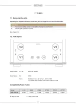
Page 20: ...the on off switch 2 Pull the grille upward to remove See chapter 3 2 7 2 Tube layout Output tubes V1 V4 basic set KT88C Driver tubes V5 6SN7 V6 V7 ECC802 ECC 82 12 AU 7 5814 6189 V 6 should have a sys...

Page 21: ...precision op amps makes it possible for you to set the BIAS to accuracy within 0 2 making it superior to any other method Using selected output tubes only makes sense if the idle current is adjusted a...

Page 22: ...OK LED on the display illuminates If the yellow LED illuminates the bias is set too high Turn the trim pot counter clockwise until the OK LED illuminates If the yellow LED illuminates the bias is set...

Page 23: ...such as the KT 88 6550 EL 34 The upper value which provides a higher BIAS current for the output tubes can be used with the KT 120 KT 150 and KT 170 in both positions of the power selector The BIAS L...

Page 24: ...New untested output tubes should be allowed a longer warm up period You should adjust these tubes after about 20 minutes and control the setting in the first days of operation 7 5 Breaking in All OCT...

Page 25: ...d This improves dynamic range separation depth soundstage size and articulation rendering the musical reproduction clearer throughout the entire frequency range The amplifier remains unaffected by mai...

Page 26: ...llow LED indicates that this procedure is taking place The discharge circuit also activates if the Super Black Box connecting cable is accidentally removed This is to prevent the Super Black Box maint...

Page 27: ...s grounding problem Tube faults caused by output tubes There are 3 different symptoms indicating a faulty output tube 1 Broken heater filament the tube stops glowing 2 Defective cathode layer the tube...

Page 28: ...Noise 100 V 150 Hz 15 KHz 116 dB Input Sensitivity 1 5 V RCA XLR Input Resistance 50 k RCA 25 k XLR CMRR of the XLR Input 85 dB 1 kHz Minimal Load Impedance 3 Gain DF Low and High 26 dB RCA Eco Mode T...

Page 29: ...D DIMENSIONS Dimensions Diagram THD at 4 V into 4 ohms from 30 Hz to 20 kHz at a variety of BIAS settings Diagramm 1 Curve 1 BIAS adjusted correctly Curve 2 BIAS 10 out Curve 3 BIAS 30 out ca 498 mm w...

Page 30: ...and efficiency of modern loudspeakers is not an issue for OCTAVE amplifiers The often quoted damping factor is not normally a guarantee that an amplifier will exert tight control over the loudspeakers...

Page 31: ...specifications in pursuit of better OCTAVE logo is a registered trade mark of Andreas Hofmann Copyright byAndreas Hofmann OCTAVEAUDIO T 49 0 7248 3278 ANDREAS HOFMANN F 49 0 7248 3279 REUTAECKERSTR 5...

Reviews: