7 Initial Operation
Instruction Manual SDI® 4 (G/54320/EN 0220 Rev01)
11 / 24
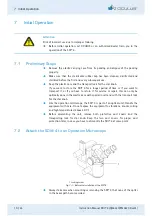
Whilst protecting the binocular tube from falling down, please
unscrew the locking screw on the main body of the microscope (1).
The SDI® 4 is generally mounted below the beam splitter.
To do so, remove the binocular tube, including the beam splitter from
the body of the microscope.
On some microscopes, the beam splitter is fully integrated into the
microscope, in which case you then have to mount the SDI® 4 above
the beam splitter.
Place the flange of the SDI® 4 into the dovetail receptacle of the
main body of the microscope. Check that the SDI® 4 is properly
seated before carefully tightening the locking screw of the main
body of the microscope. When properly mounted, the SDI® 4 should
not wobble.
Make sure of this before attaching the other microscope
components.
Proceed in the same manner when mounting the beam splitter, the
binocular eyepiece and other components of the microscope;
Carefully tighten the hexagon socket set screw of the SDI® 4
in the same way with the included hexagon screw
driver and then make sure that each component is correctly seated.
Before connecting the electrical versions of the SDI® 4 to the power
supply, check to see whether the power supply voltage is within the
voltage range given on the rating plate.
This is guaranteed if the plug-in power supply unit provided by
OCULUS is used.
Make sure that the voltage supply in the mains socket is within the
voltage range of the plug-in power supply unit.
When connecting the hand or foot switch, please do not join the
electrical plug-and-socket connections by excessive force.
After inserting the plugs into the corresponding sockets
page 12, items 3 and 4),
lock them in place by turning the threaded
connector (milled sleeve).


