background image


Ordercode: D3915 

ODIN CL-4 Connect 

Installation 

Remove all packing materials from the ODIN CL-4 Connect. Check if all foam and plastic padding is 

removed. Connect all cables. 

Do not supply power before the whole system is set up and connected properly. 

Always disconnect from electric mains power supply before cleaning or servicing. 

Damages caused by non-observance are not subject to warranty. 


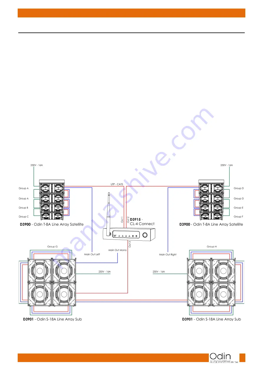
Connection Example 

Make your initial connections with all the equipment powered off and ensure that all the main volume 

controls are turned completely to the minimum. Follow the steps below. See fig. 04 for more information. 


01)


Connect one end of the XLR cable to your audio mixer (to MAIN OUT MONO) and the other end of 

the cable to the audio signal input on your first speaker. 

02)


Using an XLR cable, connect the audio signal link on your first speaker to the audio signal input on 

your second speaker. Repeat this step to connect multiple speakers. 

03)


Using a PowerCON power cord, connect the first speaker’s power input to the power supply. 

04)


Using PowerCON power cords, connect the first active speaker’s power link to the second speaker’s 

power input. Repeat this step to connect the third and fourth speaker. Please note that it is allowed 

to connect only up to 4 ODIN speakers per phase (16A). 

05)


In order to enable data signal reception, connect the CL-4 Connect to the first speaker’s RJ45 data 

input, using a UTP/CAT-5 cable. Connect the first speaker’s data link to the second speaker’s data 

input. Repeat this step to connect multiple speakers. Please note, that to ensure proper data 

reception it is allowed to connect a maximum of 12 ODIN speakers. 

06)


Use the PFL function to get the proper input level for the mixer and adjust the main mix level. 

07)


After using your equipment, turn off your active speaker cabinets first, then the mixer. 


Fig. 04 


Summary of Contents for CL-4 Connect

Page 1: ...ODIN CL 4 Connect V1 Highlite International B V Vestastraat 2 6468 EX Kerkrade the Netherlands Ordercode D3915 MANUAL ENGLISH...

Page 2: ...eturn Procedure 4 Claims 4 Description of the device 5 Overview 5 Frontside 6 Backside 7 Installation 8 Connection Example 8 Set Up and Operation 9 Connecting a Wireless Access Point and Updating 9 Co...

Page 3: ...packing Your shipment includes ODIN CL 4 Connect 5V DC power adapter User manual Safety Instructions Every person involved with the installation operation and maintenance of this system has to be qua...

Page 4: ...ting If the system has been exposed to drastic temperature fluctuation e g after transportation do not switch it on immediately The arising condensation water might damage your system Leave the system...

Page 5: ...proper UPS packing or double boxing is always a safe method to use Note If you are given an RMA number please include the following information on a piece of paper inside the box 01 Your name 02 Your...

Page 6: ...Line Array System There are 4 RJ45 ODIN data output ports for connecting up to 12 ODIN components per each output Power supply 5V DC 1000 mA Power consumption 5W Carrier frequency 2 4 GHz Data connec...

Page 7: ...ED indicators 1 4 The LEDs will blink when uninterrupted data transfer takes place LED LAN indicator Once a network has been established the LED will light up LED power indicator When the device is co...

Page 8: ...code D3915 ODIN CL 4 Connect Backside Fig 03 5V DC power connector IN RJ45 RC NET connectors 1 4 Connect your ODIN Line Array System RJ45 LAN connector IN Connect to a router in order to establish a n...

Page 9: ...ink on your first speaker to the audio signal input on your second speaker Repeat this step to connect multiple speakers 03 Using a PowerCON power cord connect the first speaker s power input to the p...

Page 10: ...PC to the CL 4 Connect via the wireless access point by connecting it to the router Follow the steps below 01 On the list of the available Wi Fi networks there will appear a new network named ODIN 02...

Page 11: ...can be found at the bottom 06 Once the connection has been established go to the Odin Editor The connection indicator should now light in green 07 Click on the CL 4 UPDATE button to open the window b...

Page 12: ...etc are caused entirely by using unsuitable or faulty cables For these applications the unit provides CAT 5 connectors to easily interface with most professional audio devices How to Make a Data Cabl...

Page 13: ...the unit operates properly do not carry out following steps 01 If the device does not operate properly unplug the device 02 Check the power from the wall all cables etc 03 If all of the above appears...

Page 14: ...13 Ordercode D3915 ODIN CL 4 Connect Notes...

Page 15: ...14 Ordercode D3915 ODIN CL 4 Connect...

Page 16: ...2016 ODIN...

Reviews: