background image

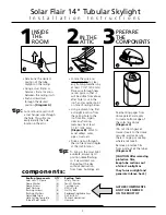
I n s t a l l a t i o n   I n s t r u c t i o n s

Please read these instructions thoroughly before installing your Solar Flair™ Tubular Skylight.

Pay particular attention to the assembly diagrams, assembly order, and part names.

(not all items shown are to scale)

FOR INSTALLATION ON AN ASPHALT ROOF 

For cathedral ceiling (12” or less) & long shaft installations (6’ or more) see Page 7.

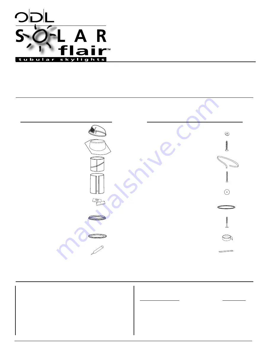
Qty

Part Description

(1)

Solar Lens™ Dome

(1)

Roof flashing

(2)

Adjustable tubes

(1)

Extension tube (20”)

(4)

Ceiling anchors

(1)

Ceiling trim ring with

screw caps

(1)

Flat ceiling diffuser

(1)

Tube of roof sealant

Qty

Part Description

(4)

Dome washers

(4)

Dome screws – 3/4"

(1)

Dome gasket – black

(8)

Flashing screws – 2"

(6)

Flashing washers

(1)

Tube ring seal – white

(4)

Drywall screws (black)

(1)

Roll of foil tape

(1)

Hole cutting template

optional components: 

SOLD SEPARATELY

ODL ITEM#

Extension tube (20”) as shown above

EZ14T20

Extension tube (48”)

EZ14T48

Prismatic ceiling diffuser

EZ14CD

White ceiling diffuser

EZ14WD

Electric light kit

EZELK

Safety Glasses 
Work Gloves
Pencil
Tape Measure
Plumb Line
Utility Knife
Phillips Screwdriver

Tin Snips
Caulking Gun
Claw Hammer
Flat Pry Bar
Power Drill
Reciprocating/Sabre Saw
Keyhole/Drywall Saw

tools required:

standard kit parts list:

hardware pack items:

14" Tubular Skylight

Summary of Contents for Solar Flair Series

Page 1: ...at ceiling diffuser 1 Tube of roof sealant Qty Part Description 4 Dome washers 4 Dome screws 3 4 1 Dome gasket black 8 Flashing screws 2 6 Flashing washers 1 Tube ring seal white 4 Drywall screws blac...

Page 2: ...before starting your installation Consult your community covenants Some subdivisions may not allow tubes on the street side of the home Before installation carefully survey the attic area of desired...

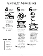
Page 3: ...the ceiling hole to the roof location Again clear any framing members by at least 7 1 4 204 mm Diagram B Work to avoid valleys wires pipes ducts etc Drive a nail up through the roof deck and shingles...

Page 4: ...les Diagram G Secure the flashing to the roof with the 2 flashing screws and washers provided 6 screws with washers are centered in pre punched star holes last 2 screws installed into remaining round...

Page 5: ...ape 1 Tube ring seal 1 TOOLS Tape Measure Tin Snips Utility Knife Place tube ring seal around adjustable tube and roll into position at flanged end Gently push tube into trim ring tube ring seal shoul...

Page 6: ...AP DISTANCE FROM TOP OF FLASHING TO FACE OF CEILING take longest measurement Less Than 15 Measure and cut adjustable tube See short shaft installation Less Than 30 Cut both adjustable tubes to fit Ass...

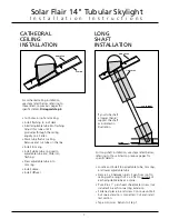
Page 7: ...ring Install dome Install diffuser CATHEDRAL CEILING INSTALLATION For long shaft installation use steps listed below referring to those listed on previous pages for specific details Locate and install...

Page 8: ...he following Adequate description of defect s Identification of Product size design type and model number Date of the Customer s purchase place of purchase and the date of delivery to the Customer 3 T...

Reviews: