background image

Echotrac CV100 

User Manual 


Page 14 of 14 

Odom Hydrographic Systems, Inc.

May 28, 2008

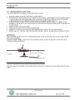
3.4 Transducer 

installation 

Proper mounting of the transducer is a crucial part of the installation of any "survey" echo sounder.  An improperly 
mounted transducer will result in poor system operation and unacceptable data quality.  
Important: See also chapter 5.5 Known problems with Transducer. 
 
In the case of temporary installations, the transducer is often mounted over-the-side.  In permanent installations 
and "pay surveys," hull mounts are generally preferred and often required.  In either case, the transducer should 
be mounted as far below the waterline as possible.  In cases where "over the side" mounts are exposed to wave 
action, ensure that the transducer is mounted far enough below the surface so that it remains well submerged 
during vessel roll motions. 
 
A preferred mounting location is near the keel of the vessel, in an area where the planing attitude of the hull and 
the pitch and roll angles of the vessel have the least effect at operating speed.  The transducer should be 
mounted far enough aft of the bow so that bubbles generated by the bow wave will not pass over the face of the 
unit.  Transducers should be located away from sources of turbulence and cavitation bubbles such as propellers, 
bow thrusters and hull protrusions.  Consideration should also be given to sources of mechanical noise generated 
within the vessel (engines, propellers, pumps, generators, etc.).  In some severe cases of mechanically coupled 
noise, vibration-isolating mounts may be required to mechanically decouple the transducer from the hull.  
 
Transducer mounting can be accomplished in many different ways.  The following three chapters show common 
configurations. 

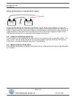
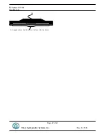
3.4.1  “THROUGH HULL” transducer installation 

The top side of the transducer is accessible from inside the vessel while the transducer face is directly exposed to 
the water. Care should be taken to protect the transducer from damage and turbulence by installing a fairing with 
a sloping forward edge ahead of the unit. The fairing has the dual effect of both minimizing possible strike 
damage and smoothing the flow of water over the face of the transducer. 
 

Figure 4: Transducer mounted through the hull 


Summary of Contents for Echotrac CV100

Page 1: ...sion 4 04 Odom Hydrographic Systems Inc 1450 Seaboard Avenue Baton Rouge Louisiana USA 70810 6261 Telephone 225 769 3051 Fax 225 766 5122 Email Odomhydrographic com http www odomhydrographic com Numbe...

Page 2: ...2008 P Oostenrijk Updated document version to match software firmware version 4 02 03 13 2008 P Oostenrijk Minor firmware change with model names 4 03 05 23 2008 P Oostenrijk Updated Scale change fun...

Page 3: ...12 3 3 Powering up the equipment 13 3 4 Transducer installation 14 3 4 1 THROUGH HULL transducer installation 14 3 4 2 SEA CHEST transducer installation 15 3 4 3 OVER THE SIDE transducer installation...

Page 4: ...l Serial Control of Echotrac Parameters 34 7 Overview parameters and settings 36 7 1 External Ethernet Control of Echotrac Parameters 36 8 Uploading Firmware 37 8 1 Upgrading Motorola Processor Firmwa...

Page 5: ...isting transducer Operator selectable TVG curves 10 Log 20 Log 30 Log 40 Log and Off serve to optimise the Echotrac for shallow bottom detection tasks and for Sonar imaging The Echotrac CV features un...

Page 6: ...SP Digital Signal Processor ETCV Echotrac CV NMEA National Marine Electronics Association SBT Single Bottom Tracking TNC Threaded Nut Connector TVG Time Varied Gain VDC Volts Direct Current 1 4 Refere...

Page 7: ...0 m s Resolution 1 m s Transducer Draft Setting 0 15m 0 50 ft Depth Display On control PC and LCD display Clock Internal battery backed time elapsed time and date clock Annotation Internal date time G...

Page 8: ...route cables using horizontal and vertical runs wherever possible Avoid paths that run adjacent to transmitter feeder cables or close to heat radiating elements such as steam pipes For permanent inst...

Page 9: ...connecting the DC power cable to any equipment Make sure that all the connecting equipment is also turned off before applying the power cables Otherwise the transients of such a jump start could dama...

Page 10: ...CV to send and receive data on the network The Echotrac CV can be connected directly to a Hub or a Switch using a regular UTP CAT 5 ethernet cable A regular cable is also known as a straight UTP cable...

Page 11: ...utting data at a slow or fast pace The Link indicator on the Echotrac CV indicates that it recognizes the presence of a network If the receiving end of the ethernet cable is connected to a computer or...

Page 12: ...at run adjacent to transmitter feeder cables or close to heat radiating elements such as steam pipes For permanent installations cables should be clamped at regular intervals 3 feet or 1 meter along t...

Page 13: ...n the connector labeled Serial 3 and the external GPS f Connect the RS232 cable between the motion sensor and the connector labelled Heave g Connect the RS232 cable between the remote display and the...

Page 14: ...effect at operating speed The transducer should be mounted far enough aft of the bow so that bubbles generated by the bow wave will not pass over the face of the unit Transducers should be located awa...

Page 15: ...clear window which is mounted flush with the hull surrounding the chest Depending on construction the material selected for the acoustic window and the draft of the vessel access can often be gained...

Page 16: ...rdy support on the vessel Lines generally are attached at the transducer pipe and tied off fore and aft in order to maintain a stable horizontal transducer attitude Care should be taken to assure adeq...

Page 17: ...epest part of the survey 11 For depths that exceed 60 feet use a bar that can reach as deep as possible In areas such as these we recommend that you use a velocimeter as a check 12 Always document and...

Page 18: ...ft equal Since the accuracy of measuring the depth depends on the value used for the velocity of sound in water along with the other factors shown above it is important that a realistic value for soun...

Page 19: ...to see a target at that 5 00 foot depth while rejecting all other returns including those from the bottom 4 Adjust the index to the correct depth 5 Change the bar depth in the Echotrac control progra...

Page 20: ...tisfy record quality requirements while at other times where local bottom conditions dictate some variation of the Transmit power Receive gain ratio a manual position may work best Note that the MAX s...

Page 21: ...t the data may not be sent out on the COM port of the Echotrac CV The Echotrac CV could be in Standby mode 8 Try powering down the Echotrac CV and powering it back up again If the Echotrac CV is turne...

Page 22: ...Echotrac CV100 User Manual Page 22 of 22 Odom Hydrographic Systems Inc May 28 2008 TRANSDUCER FACE Air trapped under a thin film layer on the face of the transducer...

Page 23: ...422 The COM ports on the Echotrac CV is capable of sending and receiving data in RS232 only In its standard configuration the unit sends ASCII characters at 9600 baud 8 data bits 1 start bit 1 stop b...

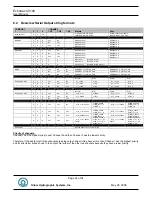
Page 24: ...X X X No Yes No _et__12345 _etE_0 _ET__12345 _ETE_0 X X X No No Yes _et__12345 _etE_0 _ET__12345 _ETE_0 Normal Error Normal Error ECHOTRAC DBT X X X Yes No No _et_H_11111 _etEH_0 _ET_H_11111 _ETEH_0 X...

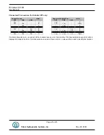
Page 25: ...CH3 CH1 CH2 CH3 Yes H 9 e E Yes Yes B 9 e 9 o D all Yes L 9 e E Yes Yes B 9 e 9 o E Yes Yes B 9 e 9 o E Yes Yes Yes C 9 e 9 o 9 f G all If multiple channels are in use and not all the channels have a...

Page 26: ...2 E units are in tenths of feet e units are in centimeters 3 T units are in tenths of feet t units are in centimeters 4 Normally a Space an E indicates Error 5 Always a space 6 Depth Data MSD 7 Depth...

Page 27: ...ark 2 E units are in tenths of feet e units are in centimeters 3 T units are in tenths of feet t units are in centimeters 4 Normally a Space an E indicates High Frequency error and an O indicates Low...

Page 28: ...equency error and an O indicates Low Frequency error missed return D indicates High and Low error missed returns 5 B Frequency Indicator Both High and Low 6 Always a space 7 Depth Data High Frequency...

Page 29: ...ways Centimeter Resolution 17 CR Carriage Return Example sp etEH sp DDDDD HHHH CR The following description applies to the selection of HEAVE while both frequencies high and low are active HEAVE Two F...

Page 30: ...pplies to the selection of DESO DDV while only one frequency either high or low is active Once every 2 seconds the following two strings will also be output immediately after the DESO 25 outputstring...

Page 31: ...selected TXx 80 characters max xCL example TXthis is a test VSsxx xx_m sCL example VS 01 23 m s EMxCL example EM0 EM1 EM2 or EM3 CL Terminator command x single character s sign or C Carriage Return L...

Page 32: ...20 space Care should also be taken to avoid annotation overrun which is caused by grouping annotated events so closely together that they obscure the record Header Information multiple line annotatio...

Page 33: ...e string TSS1 String Character Character Description 1 Start Character 2 3 X Horizontal acceleration data 4 7 A Vertical acceleration data 8 sp Space 9 sp Space if positive minus if negative 10 13 H H...

Page 34: ...Parameter SPACE New Value Delimiter Byte 1 2 3 4 5 6 7 8 9 10 11 12 13 HEX 0x10 DLE 0x00 0xFF 0x00 0xFF 0x20 n n n n n n n n 0x0D CR DEX 16 0 255 0 255 32 n n n n n n n n 13 Note HEX Hexadecimal DEC D...

Page 35: ...value request The Echotrac CV will then reply with CV3 P UNITS PING NUMBER PARAMETER ID VALUE The Units is a single character F or M for Feet or Meters The ping number is 8 characters the Parameter I...

Page 36: ...ings can be found in reference 3 Any setting that is changed in the control program is automatically sent to the Echotrac 7 1 External Ethernet Control of Echotrac Parameters The Echotrac ETHERNET por...

Page 37: ...d in order for the flash upgrade to work 1 Install the Odom Flash Utility by Unzipping the OdomFlash zip file in a directory After the file is uncompressed run the setup exe file to install the progra...

Page 38: ...op of the transceiver boards There one DSP board for each transceiver board in the Echotrac 4 Connect the DSP flash cable to JP13 of the DSP 5 Move shunt on JP10 from the left two pins to the right tw...

Page 39: ...22 Connector PN Pin Number Signal Description DB9 Male 2 Transmitted data from Echotrac 3 Received data to Echotrac 5 GND 9 3 Serial 3 Serial 3 is used for interfacing a positioning system to the Echo...

Page 40: ...cer or a signal frequency transducer connect the transducer here Connector PN Pin Number Signal Description MS3116J14 5P A Shield B High Frequency C Low Frequency D Low Frequency E High Frequency 9 7...

Page 41: ...2 RS 232 Input 3 RS 232 Output 5 Shield Signal ground Common return POWER Cable Conn DC only P N MS3114E12 3P Pin Description A 12 or 24 VDC B No Connection C Return Fuse 5 amp DC inputs only Standar...

Page 42: ...Ethernet TX RX LED should start blinking as well as one or both of the Transmit High Low LEDs If this does not happen then the Echotrac CV100 is in Standby Mode Use the Odom eChart Program to start th...

Page 43: ...rac CV100 User Manual Page 43 of 43 Odom Hydrographic Systems Inc May 28 2008 P P Pa a ag g ge e e l lle e ef f ft t t b b bl lla a an n nk k k i iin n nt t te e en n nt t ti iio o on n na a al lll ll...

Reviews: