background image

TM

®

ASSEMBLY INSTRUCTIONS

Summary of Contents for Z01T

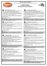
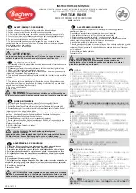
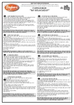
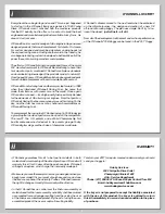
Page 1: ...TM ASSEMBLY INSTRUCTIONS ...

Page 2: ...rom over O Donnell took his vast knowledge of nitro engine tuning and soon designed products that would complement his talents First came his custom designed and machined aluminum cooling heads for the on road racing scene Finding another void in the industry he also began producing custom tuned pipes to better utilize all of the power these nitro burning monsters could produce The efforts of O Do...

Page 3: ...you read and follow all of the precautions on the fuel container Keep fuel out of the reach of children Model engine fuel is flammable and when ignited has a flame that is difficult to see Avoid sparks flames smoking or any other ignition source when fuel is near The engine emits harmful fumes just like real vehicles Do not operate this model indoors Avoid running the truggy in cold weather The pl...

Page 4: ...4 4 4 v REQUIRED ACCESSORIES Servo High Torque Steering Servo 5 Cell Receiver Hump Pack Tire Inserts Header Pipe Tires Engine Receiver Transmitter Glow Plug and spares ...

Page 5: ...T Threadlock CA Tire Glue Diff Shock Air Filter Oils 3 0mm Hex Wrench 2 5mm Hex Wrench 2 0mm Hex Wrench 1 5mm Hex Wrench Hobby Knife Glow Plug Ignitor Snap Ring Pliers Flywheel Wrench Body Scissors Fuel 4 Way Wrench Clutch Tool Fuel Bottle ...

Page 6: ...grease in the groove and a light film of grease on the shaft of all outdrives Front Rear x2 Center x1 Apply a small amount of included grease to the O ring before installing This will help prevent damage to the O ring when installing the drive joint Satellite Backing Washer x12 8x16mm Bearing x3 Diff Outdrive O Ring x3 Sun Backing Washer x3 Slide the pin in place using needle nose pliers Grease Gr...

Page 7: ...gear is mounted flat on the diff housing and the housing is properly sealed 1 2 3 4 Center x1 D I F F O I L D I F F O I L 8x16mm Bearing x3 Diff Outdrive O Ring x3 Sun Backing Washer x3 3x12mm FH Screw x12 Grease 1 1 Build the front rear and center diffs Make sure the bearing is fully seated on the gear Front Rear x2 Apply a small amount of the included grease to the O ring before installing This ...

Page 8: ...all 3x8mm FH 4x14mm FH 4x14mm FH x2 x4 x4 Front Line up brake disc notch 16 75mm 2 2 IMPORTANT IMPORTANT The grooves for the diff bearings face inward Make sure the brake disc guides are interlocked with the diff mounts before installing IMPORTANT IMPORTANT Brake pad bolt adjustment must be correct and equal front and rear ...

Page 9: ...filter mount to the center upper brace before installing the center upper brace to the center diff mounts IMPORTANT IMPORTANT Make sure the brake actuators move freely in the mounts Long Short Threadlock Threadlock 3x35mm BH Screw 5x8mm Flanged Bearing 3x4mm Set Screw 3x8mm BH Screw 3x35mm BH x4 x2 x2 x2 2 Front 5 5mm 4 25mm HARDWARE ...

Page 10: ...trip of the included grease to three locations on the ring gear Make sure the bearings are fully seated in the case Threadlock 4x14mm FH 3x14mm FH 4x8mm SS 4x14mm FH Screw x2 8x16mm Bearing x2 5x5mm Set Screw x1 3x14mm FH Screw x2 4x16mm BH Screw x2 Gold Thin Diff Shim x2 Silver Thick Diff Shim x2 4x40mm FH Screw x2 4x8mm Set Screw x2 Pinion Shaft Shim x2 3 3 G rease G rease Grease Grease Grease L...

Page 11: ...the hub Secure the axle pin in the drive hub using the 5mm set screw Place the O ring in the groove after installing the wheel hub pin T h r e a d l o c k 4x14mm FH Screw 3x14mm FH Screw 3x14mm FH 3x14mm BH 4x14mm FH x2 x4 3x14mm BH Screw x2 Wheel Hub Pin x2 8x16mm Bearing x4 O Ring x2 5x5mm Set Screw x2 3 3 ...

Page 12: ...20mm FH 3x25mm BH Screw x2 3x6mm BH Screw x2 Standard Rod End Ball x4 3mm Washer x2 3x18mm SH Screw x2 3mm Lock Nut x4 Outer Lower Rear Hinge Pin x2 x2 x2 x4 x4 Threadlock Threadlock Secure the hinge pin in place with the 3x6mm BH screw Notched link end faces up for wheel clearance Front of truggy 3x25m m FH 3x25m m FH 3x10m m BH 3x10m m BH 3x25mm BH 3x18mm SH 3 4 ...

Page 13: ...H Screw 3x20mm BH 3x25mm SH 3x25mm SH 4x30mm BH x4 4x10mm Set Screw x2 3x3mm Set Screw x2 End Ball x2 3x20mm BH Screw x2 3x25mm SH Screw x2 4x30mm BH Screw x1 Threadlo ck 2 5x8mm SH 4mm Lock Nut x1 4x10mm SS 3x3mm SS 3 3 IMPORTANT IMPORTANT There are three sizes of swaybars and swaybar bushings Be sure to use the correct bushing with its corresponding swaybar Rear Swaybar Bushing Soft 093 OD Small...

Page 14: ...asket between the gearbox and chassis Make sure the tabs on the bottom of the gearbox key into the chassis Install a 2mm dogbone spacer inside the drive cup of the center differential 4x12mm FH Screw 3x25mm BH Screw 3x25mm BH Rear Bumper 4x12mm FH 3x16mm BH 3x8mm FH x4 x1 3x8mm FH Screw x2 Threadlock 3x16mm BH Screw x1 3mm Lock Nut x1 Standard Rod End Ball x2 3 3 ...

Page 15: ...mm SS IMPORTANT IMPORTANT Apply a 1 4 strip of the included grease to three locations on the ring gear Use the included shims to space gears properly in the diff case Adjust the gear mesh for smooth rotation without excessive play The number of shims needed and the side on which they must be placed may vary Gold Thin Diff Shim x2 Silver Thick Diff Shim x2 G r e a s e G r e a s e G r e a s e G reas...

Page 16: ...H 3x14mm FH 3x25mm SHCS 3x14mm BH 4x11mm BH 4x11mm BH 5x5mm SS x4 x2 x4 x2 4x11mm BH Screw x4 Wheel Hub Pin x2 8x16mm Bearing x4 5x5mm Set Screw x2 Threadlock Threadlock 10 Caster Block 5 5 Make sure the bushings are fully seated in the shock tower Bushing A centered Place the O ring in the groove after installing the wheel hub pin O Ring x2 IMPORTANT IMPORTANT Thoroughly clean screws of oil befor...

Page 17: ...INKS HARDWARE 3x6mm BH 3x6mm BH Screw x2 Outer Lower Front Hinge Pin x2 3x25mm BH Screw x2 3x10mm FH Screw x6 Standard Rod End Ball x2 3mm Lock Nut x6 5 Make sure to use the correct part Note the direction 3x25m m BH 3x10mm FH 5 3x10mm FH Actual Size 10mm ...

Page 18: ...rew 3mm Lock Nut 4x8mm FH Screw 3x16mm BH Screw Note the direction of the arms Trim this edge if there is interference at full steering 3x16mm FH 3x16mm BH 3x14mm FH 4x8mm FH x2 x2 x2 x4 x1 x4 x1 x3 Threadlock 3x14mm FH 6 Actual Size 66mm Make sure the bearings are fully seated 4mm Servo Saver Trimmed Edge Threadlock Threadlock ...

Page 19: ...box key into the chassis 3x16mm BH 3x16mm BH 4x12mm FH 3x8mm FH 3x8mm FH Screw x2 Standard Rod End Ball x2 3x16mm BH Screw x2 Make sure the dogbone is placed under the steering rack bar Install a 1 5mm dogbone spacer inside the center diff drive cup 7 7 HARDWARE 4x12mm FH Screw x2 Position the gasket between the gearbox and chassis ...

Page 20: ...hings Be sure to use the correct bushing with its corresponding swaybar Front Swaybar Bushing Soft 093 OD Small Medium 100 OD Medium Firm 105 OD Large 20 20 28 FRONT SWAYBAR LINKS HARDWARE Make sure the left and right swaybar links are set at equal distances from the end of the swaybar rod 4x10mm Set Screw x2 3x3mm Set Screw x2 End Ball x2 3x20mm BH Screw x2 3x3mm SS 2 5x8mm SH 4x10mm SS 3x20mm BH...

Page 21: ... different types of servos spacer size may vary Spacer Spline Adapter 8 29 FRONT BUMPER HARDWARE Threadlock Threadlock Make sure the steering link is mounted on top of the knuckle arm 4x12mm FH 3x18mm BH 3x8mm FH 3x6mm FH 3x16mm FH 3x16mm FH 4x8mm FH 3x18mm BH Screw x2 3mm Lock Nut x2 4x8mm FH Screw x2 3x8mm FH Screw x2 3mm Washer x6 4x12mm FH Screw x2 Use three 3mm washers to minimize bump steer ...

Page 22: ...T 3mm Futaba DuraTrax 25T 3mm Hitec Hobbico 24T 1mm KO Propo 23T 2mm JP Propo 23T 2mm Due to different types of servos spacer size may vary Included with radio system Install the small grommet in the antenna wire hole to help keep dirt out of the radio box Switch screws come with switch Do not overtighten hinge screws 8 8 Note orientation of the servo Servo not included Spacer 2x8mm SH ...

Page 23: ...STS HARDWARE 23 23 34 SERVO TRAY HARDWARE 3x8mm FH Screw 3x10mm FH Screw 3x8mm FH Screw 3x10mm FH Screw 3x8mm FH 3x8mm FH 3x8mm FH 3x10mm FH 3x10mm FH 3x10mm FH x2 x4 x2 x2 Threadlock Threadlock Threadlock Threadlock 8 8 ...

Page 24: ...x1 3x10mm BH Screw x1 3x3mm Set Screw x6 3x16mm BH Screw x1 8 37 5mm 2mm THROTTLE LINKAGE Threadlock Pivot A Pivot B BRAKE LINKAGES Threadlock Pivot A Pivot B Do not overtighten these screws Make sure the pivots can move and turn freely 3x16mm BH 3x10mm BH 19 25mm 2mm Threadlock on all set screws ...

Page 25: ...BH Screw x1 Secure the antenna tube to the radio box using a 3x6mm BH screw Do not overtighten Route the receiver antenna wire through the antenna grommet in the side of the receiver box and into the antenna tube We recommend using Velcro to secure the battery and receiver to the radio box Rx Battery Rx 8 9 IMPORTANT IMPORTANT Make sure you do not overtighten the 3x18mm FH fuel tank screw The tank...

Page 26: ...mm FH Screw x8 9 38 TUNED PIPE MOUNT HARDWARE 4x4mm Set Screw 4x12mm FH Screw x1 x1 Depending on which pipe and header are used you may need to cut the end of the pipe mount wire to fit 9 Threadlock Threadlock 4x12mm FH 3x10mm FH 3x10mm FH ...

Page 27: ...mm SH Washer 4x12mm FH 4x12mm FH x4 x4 x4 27 27 41 FLYWHEEL Threadlock Threadlock 9 10 Make sure the collet is all the way on the engine s crankshaft before installing the flywheel and clutch nut ENGINE SOLD SEPARATELY ENGINE SOLD SEPARATELY IMPORTANT IMPORTANT Use threadlock on all four 4x10mm SH washer screws ...

Page 28: ...CH HARDWARE 5x10mm Bearing x2 Clutch Shim x4 3mm SH Screw with Washer x1 Shim the clutch bell to allow minimal end play The number of shims may vary 10 HEADER AND PIPE ASSEMBLY HEADER AND PIPE ASSEMBLY SOLD SEPARATELY SOLD SEPARATELY ...

Page 29: ... Screw x4 29 29 45 THROTTLE LINKAGE Snap the throttle linkage ball end onto the carb arm Place a strip of paper between the spur and clutch bell to help properly set the gear mesh Once the gear mesh is set remove the paper Threadlock 10 3x14mm SH ...

Page 30: ... x4 2 5mm Washer x4 11 11 IMPORTANT IMPORTANT Make sure the snap ring is securely seated in the groove Rear Long x 2 Front Short x 2 14mm Shock Wrench 20mm Shock Wrench IMPORTANT IMPORTANT When installing the shock cartridge into the shock body be sure to not cross thread the cartridge in the shock body Press the shock cartridge into the bottom of the shock body and rotate the cartridge backwards ...

Page 31: ...OCK OIL SHOCK OIL S L O W L Y S L O W L Y SHOCK OIL SHOCK OIL Fill the shock body with shock oil with shock shaft fully extended oil level should be just below the top of the shock body Gently work the shaft up and down in the shock body to allow the air bubbles to work out of the oil x 4 IMPORTANT IMPORTANT To avoid damage DO NOT overtighten or use the hole in the cap when installing the cap on t...

Page 32: ...l the shock boot over the shock end and secure it in place on the shock body Gently work the shock end out the bottom of the shock boot The bottom of the shock boot should be firmly in place around the top of the shock end x 4 Make sure the spring retainer keys onto the tab on the shock end Rear Long x 2 Front Short x 2 Thread the adjustable collar onto the shock body 11 11 3x20mm BH ...

Page 33: ...TUBING Install fuel tubing as shown making sure it is not close to any moving parts or kinked Fuel tubing not included 52 REAR SHOCK INSTALLATION HARDWARE 3x20mm BH Screw x2 3mm Lock Nut x2 3mm Lock Nut x2 11 3x20mm BH ...

Page 34: ...MPORTANT Place the inner element into a small plastic bag and soak with air filter oil not included Work the oil into the element until it is completely saturated Remove the element from the bag and remove the excess oil from the filter using a clean rag or paper towel Secure the air filter assembly to the air filter boot with one of the included tie straps ...

Page 35: ...35 56 TIRE AND WHEEL INSTALLATION HARDWARE Wheel Nut x4 Tires and inserts sold separately 35 35 57 BODY 14 Trim body as shown ...

Page 36: ...Copyright 2009 ODOZ1010 for ODOC0125 ...

Reviews: