91
SER
IES K
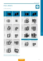
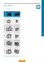
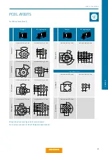
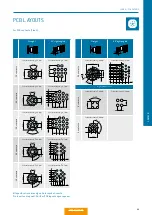
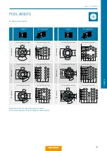
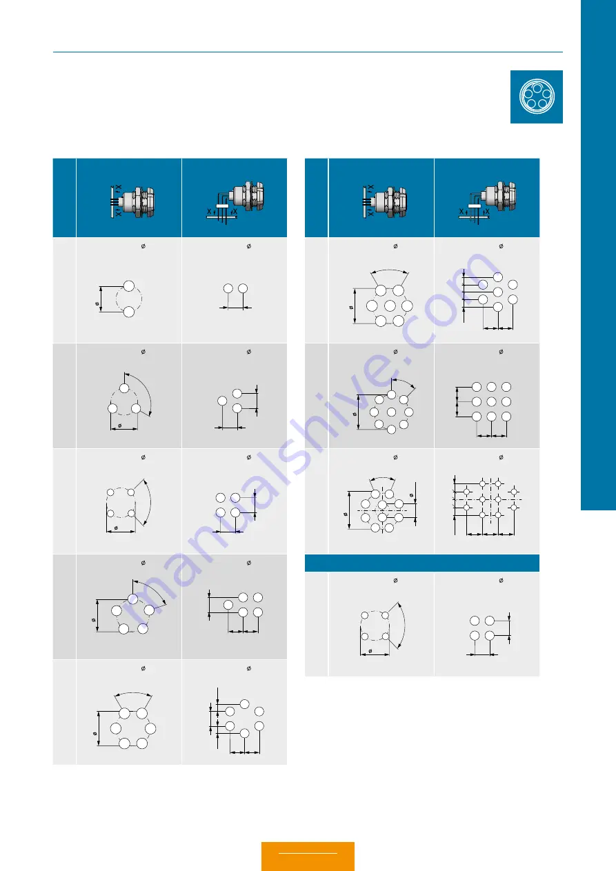
PCB LAYOUTS
Straight
90° right-angled
2 c
on
tac
ts
Contact borehole: 0.8 mm
Contact borehole: 0.7 mm
3 c
on
tac
ts
Contact borehole: 0.8 mm
Contact borehole: 0.7 mm
4 c
on
tac
ts
Contact borehole: 0.6 mm
Contact borehole: 0.7 mm
5 c
on
tac
ts
Contact borehole: 0.6 mm
Contact borehole: 0.7 mm
6 c
on
tac
ts
Contact borehole: 0.6 mm
Contact borehole: 0.7 mm
1
2
2.2
1
2
2.54
3 ×
12
0°
1
2
3
2.3
4
×9
0°
2.5
1
2
3
4
5 ×
72°
2.8
1
2
3
4
5
6 ×60°
2.8
1
2
3
4
5
6
2.5
4
2.54
1
2
3
2.5
4
2.54
1
2
3
4
25
4
2.54 2.54
1
2
3
4
5
2.5
4
1.
27
1.
27
2.54 2.54
1
2
3
4
5
6
For PCB contacts (Size 0).
All speci
fi
cations are only valid for socket inserts.
Pin inserts on request. Further PCB layouts upon request.
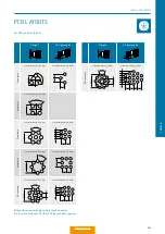
Straight
90° right-angled
7 c
on
tac
ts
Contact borehole: 0.6 mm
Contact borehole: 0.7 mm
9 c
on
tac
ts
Contact borehole: 0.6 mm
Contact borehole: 0.6 mm
10 c
on
ta
ct
s
Contact borehole: 0.6 mm
Contact borehole: 0.7 mm
High-speed version
4 c
on
tac
ts
Contact borehole: 0.6 mm
Contact borehole: 0.7 mm
3
6 ×60°
1
2
3
4
5
6
7
2.54 2.54
1.
27
1
2
3
4
5
6
7
8×45°
1
2
3
4
5
6
7
8
9
3
1.
27
1
8
5
4
2
3
9
10
7
6
2.54 2.54 2.54
8×45°
1
2
3
4
5
6
7
8
9
10
3.3
1.
15
2.54 2.54
2.5
4
2.5
4
1
2
3
4
5
6
7
8
9
4
×9
0°
2.5
1
2
3
4
2.5
4
2.54
1
2
3
4
SERIE K – PCB LAYOUTS
Summary of Contents for MINI-SNAP K Series
Page 10: ...ODU MINI SNAP Table of Contents...
Page 16: ...ODU MINI SNAP Table of Contents...
Page 17: ...CONFIGURATION GUIDELINE Correct configuring step by step CONFIGURATION Table of Contents...
Page 22: ...ODU MINI SNAP Table of Contents...
Page 37: ...89 SERIES K SERIES K FOR YOUR NOTES Table of Contents...
Page 55: ...107 SERIES K SERIES K FOR YOUR NOTES Table of Contents...
Page 61: ...113 SERIES K SERIES K FOR YOUR NOTES Table of Contents...
Page 62: ...ODU MINI SNAP Table of Contents...


