166
TECHNICAL INFORMATION
The American Wire Gauge (AWG) is based on the principle that
the cross-section of the wire changes by 26% from one gauge
number to the next. The AWG numbers decrease as the wire di-
ameter increases, while the AWG numbers increase as the wire
diameter decreases. This only applies to solid wire.
However, stranded wire is predominately used in practice. This
has the advantage of a longer service life under bending and vi-
bration as well as greate
r fl
exibility in comparison with solid wire.
Stranded wires are made of multiple, smaller-gauge wires
(higher AWG number). The stranded wire then receives the AWG
numbers of a solid wire with the next closest cross-section to
that of the stranded wire. In this case, the cross-section of the
stranded wire refers to the sum of the copper cross-sections of
the individual wires.
Accordingly, strands with the same AWG number b
ut diff
erent
numbers of wire
s diff
er in cross-section. For instance, an AWG
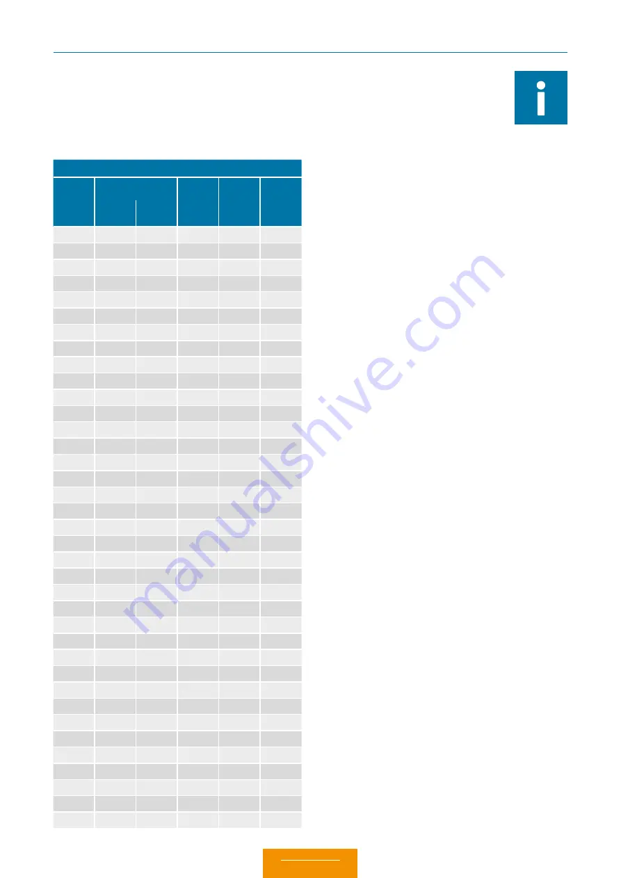
20 strand of 7 AWG 28 wires has a cross-section of 0.563 mm
2
,
while an AWG 20 strand of 19 AWG 32 wires has a cross-section
of 0.616 mm
2
.
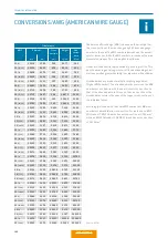
CONVERSIONS/AWG (AMERICAN WIRE GAUGE)
Source: ASTM
Circular wire
AWG
Diameter
Cross-
section
mm
2
Weight
kg / km
Max.
resist-
ance
Ω /km
Inch
mm
10
(1)
0.1019
2.590
5.26
46.77
3.45
10
(37/26)
0.1150
2.921
4.74
42.10
4.13
12
(1)
0.0808
2.050
3.31
29.41
5.45
12
(19/25)
0.0930
2.362
3.08
27.36
6.14
12
(37/28)
0.0910
2.311
2.97
26.45
6.36
14
(1)
0.0641
1.630
2.08
18.51
8.79
14
(19/27)
0.0730
1.854
1.94
17.23
9.94
14
(37/30)
0.0735
1.867
2.08
18.870
10.50
16
(1)
0.0508
1.290
1.31
11.625
13.94
16
(19/29)
0.0590
1.499
1.23
10.928
15.70
18
(1)
0.0403
1.020
0.823
7.316
22.18
18
(19/30)
0.0052
1.321
0.963
8.564
20.40
20
(1)
0.0320
0.813
0.519
4.613
35.10
20
(7/28)
0.0390
0.991
0.563
5.003
34.10
20
(19/32)
0.0420
1.067
0,616
5.473
32.00
22
(1)
0.0253
0.643
0,324
2.883
57.70
22
(7/30)
0.0288
0.732
0,324
2.965
54.80
22
(19/34)
0.0330
0.838
0.382
3.395
51.80
24
(1)
0.0201
0.511
0.205
1.820
91.20
24
(7/32)
0.0250
0.635
0.227
2.016
86.00
24
(19/36)
0.0270
0.686
0.241
2.145
83.30
26
(1)
0.0159
0.404
0.128
1.139
147.00
26
(7/34)
0.0200
0.508
0.141
1.251
140.00
26
(19/38)
0.0220
0.559
0.154
1,370
131.00
28
(1)
0.0126
0.320
0.0804
0.715
231.00
28
(7/36)
0.0160
0.406
0.0889
0.790
224.00
28
(19/40)
0.0170
0.432
0.0925
0.823
207.00
30
(1)
0.0100
0.254
0.0507
0.450
374.00
30
(7/38)
0.0130
0.330
0.0568
0.505
354.00
30
(19/42)
0.0123
0.312
0.0720
0.622
310.00
32
(1)
0.0080
0.203
0.0324
0.288
561.00
32
(7/40)
0.0110
0.279
0.0341
0.303
597.10
32
(19/44)
0.0100
0.254
0.0440
0.356
492.00
34
(1)
0.0063
0.160
0.0201
0.179
951.00
34
(7/42)
0.0070
0.180
0.0222
0.197
1,491.00
36
(1)
0.0050
0.127
0.0127
0.1126
1,519.00
36
(7/44)
0.0060
0.150
0.0142
0.1263
1,322.00
Summary of Contents for MINI-SNAP K Series
Page 10: ...ODU MINI SNAP Table of Contents...
Page 16: ...ODU MINI SNAP Table of Contents...
Page 17: ...CONFIGURATION GUIDELINE Correct configuring step by step CONFIGURATION Table of Contents...
Page 22: ...ODU MINI SNAP Table of Contents...
Page 37: ...89 SERIES K SERIES K FOR YOUR NOTES Table of Contents...
Page 55: ...107 SERIES K SERIES K FOR YOUR NOTES Table of Contents...
Page 61: ...113 SERIES K SERIES K FOR YOUR NOTES Table of Contents...
Page 62: ...ODU MINI SNAP Table of Contents...

