169
TECHNICAL INFORMATION
TE
CHN
IC
AL I
NF
ORMA
TI
ON
Electromagnetic compatibility (EMC) concerns more than just devices and electronic circuits. In the age of networks
and data communication, connecting elements such as cables and connectors are also very important. Interference
signals penetrating the connector from outside corrupt data signals and can cause si
gnifi
cant system malfunctions.
This can be reliably avoided with high-grade shielding for the cables and connectors. In order to give our customers
certainty when using ODU MINI-SNAP connectors, we’ve had a size 3 connector measured by an accredited EMC labora-
tory to determine its EMC quality. Since the sizes 0, 1 and 2 are identical to this connector in structure, just propor-
tionally reduced in size, the values for shielding attenuation are the same.
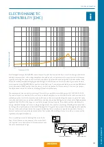
The measurement was conducted according to the injection or parallel wire method pursuant to VG 95214-11:2002.
The connector pair is connected to the receiver of a network analyzer on one end, while the other end receives an ad-
justed termination resistor. The injection wire is attached as closely as possible along the connector pair
. A fl
at cable
is usually used here, since an optimum adjustment can be achieved by attaching more or fewer wires. High-frequency
signals in the 10 kHz to 3 GHz range are now fed in through the injection wire. The network analyzer measures the
energy irradiated through the connector plug housing and into the connector, providing a shielding attenuation factor
as the logarithmic performance ratio AT in dB. The important thing with this method is that all supply lines (especially
the ones to the connector pair) must be very well shielded so that no interference signals can penetrate the meas-
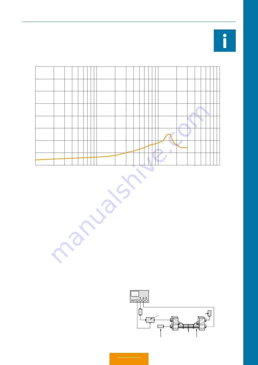
urement system and corrupt the measured values. This provides the shielding attenuation in dB as a curve over the
logarithmically applied frequency.
Users frequently demand a shielding attenuation better
than –55 dB (based on a requirement of Deutsche Post).
It is clear that our connector meets this requirement over
the entire measurement range.
ELECTRO MAGNETIC
COMPATIBILITY (EMC)
Shi
el
din
g a
tt
en
ua
tio
n in dB
Frequency in GHz
0
-10
-20
-30
-40
-50
-60
-70
-80
Attenuater
20
dB
Ne
two
rk an
alyzer
Power splitter
Te
rmination impedance
Te
rmination impedance
In
ductive wire
Couple
r
Couple
r
Object un
der test
Ta
pe
0.01
1.00
10.00
Summary of Contents for MINI-SNAP K Series
Page 10: ...ODU MINI SNAP Table of Contents...
Page 16: ...ODU MINI SNAP Table of Contents...
Page 17: ...CONFIGURATION GUIDELINE Correct configuring step by step CONFIGURATION Table of Contents...
Page 22: ...ODU MINI SNAP Table of Contents...
Page 37: ...89 SERIES K SERIES K FOR YOUR NOTES Table of Contents...
Page 55: ...107 SERIES K SERIES K FOR YOUR NOTES Table of Contents...
Page 61: ...113 SERIES K SERIES K FOR YOUR NOTES Table of Contents...
Page 62: ...ODU MINI SNAP Table of Contents...


