background image

Reference/System

 Series

TOYOTA    Tacoma
Procedure

Issue C 09/15/19

Page | 17

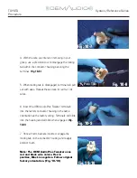
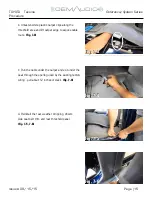
g. You will be left with the remote cable, the 20-
pin connector of the Quick-Sync Wiring Harness 
and the 8-pin connector of the Subwoofer Umbilical 
underneath the driver’s side seat. 

(Fig. 8-7)

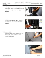
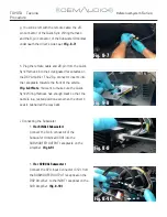
h. Plug the remote cable and 20-pin from the Quick-
Sync Harness into their designated receptacles on 
the DSP Ampli

fi

er. The 20-p connector inserts into 

the receptacle towards the front of the vehicle.

(Fig. 8-8) Note

: You want to make sure the Quick-

Sync Wiring Harness has enough slack so that the 
cable is in a rested position even when the driver’s 
seat is pushed all the way back. 

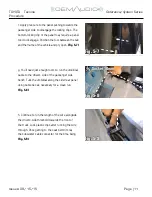
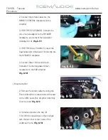
i. Connecting the Subwoofer :


1.

 (For SINGLE Subwoofer)

Connect the 8-pin connector of the 
Subwoofer Umbilical (C09) into the 
SUBWOOFER OUTPUT receptacle on the 
Ampli

fi

er. 

(Fig 8-9) 

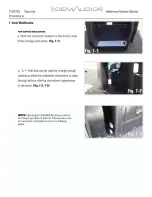
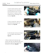
1. 

(For SP/DUAL Subwoofer)

Connect the SPU-Input Connector (C12) from 
the SUBWOOFER OUTPUT receptical on the 
DSP Ampli

fi

er, to the INPUT receptical on the 

SUB Ampli

fi

er. 

(Fig. 8-10)

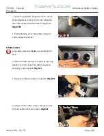
Fig. 8-7

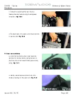
Fig. 8-8

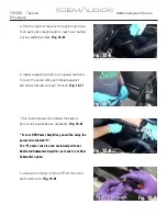
Fig. 8-9

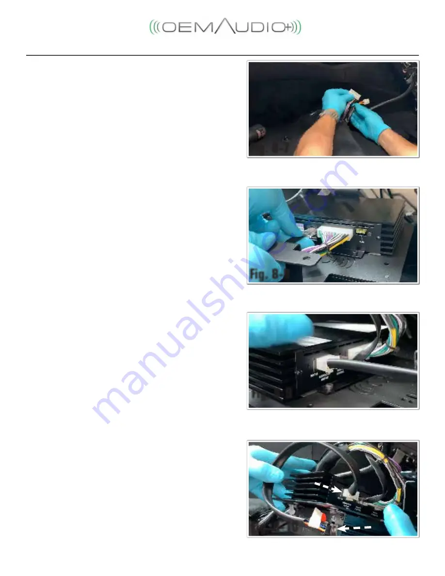
Fig. 8-10

subwoofer

 output

   input

Summary of Contents for Reference Series

Page 1: ...t Safety Gloves Special Tools Notes Panel Clip Removal SST 00002 06001 01 Socket Wrench Sockets 10mm 14mm Socket Extension 6 Screwdriver 2 Phillips Side Cutters Wire Strippers Needed for 12g butt Seal...

Page 2: ...ity installation These guidelines can be found in the Accessory Installation Practices document This document cover such items as Vehicle Protection use of covers and blankets cleaning chemicals etc S...

Page 3: ...ery cable d Prepare a protective surface to place all vehicle components on Section 2 is for Reference 400CF Only 2 Front Door Speaker Installation a Remove Door Panels 1 Remove A Pillar by pulling st...

Page 4: ...d the interior door latch Fig 2 6 6 Remove 2 Phillips screw behind the door latch 7 Use a pick tool to remove the cover below door grab handle and remove the 2 Phillips screw behind the cover 8 Use pa...

Page 5: ...g 2 9 3 Mount the 6x9 OEM Audio Plus speaker by using the four 10mm bolts and re install 6x9 speaker connector c Install OEM Audio Plus 1 Tweeter 1 Remove the two 10mm bolts holding the factory speake...

Page 6: ...The red wires are positive and the black wires are negative Fig 10 4 2 Carefully remove the connector exterior foam Fig 10 5 3 With a precision screwdriver or pick tool lift the locking tab of the fac...

Page 7: ...actory wiring Terminals will slide into the housing and will click when engaged Fig 10 9 7 Once all terminals are inserted engage the locking tab on the connector housing and reapply exterior foam Not...

Page 8: ...ee included addendum d Reassemble door in reverse order taking time to ensure all clips are engaged Section 3 is for Reference 400CF Only 3 Rear Door Speaker Installation a Remove door panels 1 Use a...

Page 9: ...Fig 3 4 6 Use a panel tool to remove the window control panel Fig 3 5 7 Disconnect window control connector from the panel 8 Use gentle force to remove door panel Start at the bottom then the sides a...

Page 10: ...are engaged Failure to securely reinstall door panel may result in rattles 4 Prepping for subwoofer umbilical run a Remove the drivers side rear threshold by pulling in an upward motion Fig 4 1 b Remo...

Page 11: ...e lower portion of the panel and working your way up disengage clips Fig 4 4 f Check for white snaps that may not have come off with the panel Re insert to panel if applicable Fig 4 5 5 Subwoofer Inst...

Page 12: ...ocket remove the three 10mm bolts securing the rear storage panel from behind the drivers side rear seat Fig 5 4 d Hold the panel and disengage the front and top edge snaps one at a time while simulta...

Page 13: ...Tuck the umbilical along the side rear panel using cable ties as necessary for a clean run Fig 5 8 h Continue to run the length of the wire alongside the drivers side threshold towards the front of th...

Page 14: ...03 637 0463 05 0QFOJOH GPS 426 3 ODMPTVSF XJMM CF PO 1BTTFOHFS 4JEF PG 7FIJDMF 1MFBTF UBLF OPUF PG DPOOFDUPS PSJFOUBUJPO QSJPS UP NPEJGZJOH QBOFM...

Page 15: ...JH...

Page 16: ......

Page 17: ...nd lift carpet edge to expose cable route Fig 7 3 c Run the cable under the carpet and exit under the seat through the opening used by the existing factory wiring pull about 12 inches of slack Fig 7 4...

Page 18: ...driver side kick panel by unscrewing the black locking tab Fig 8 2 3 Continue routing the Quick Sync Wiring Harness radio connects and power wire towards the driver sidekick panel area Use cable ties...

Page 19: ...om the carpet opening Fig 8 6 6 Locate the factory ground underneath the carpet and remove the 10mm ground bolt Fig 8 7 7 Install the harness ground together with the factory ground and re install the...

Page 20: ...eptacle towards the front of the vehicle Fig 8 8 Note You want to make sure the Quick Sync Wiring Harness has enough slack so that the cable is in a rested position even when the driver s seat is push...

Page 21: ...ical C16 directly into the SPEAKER receptacle 4 Connect Power Ground Green Connector to the designated Green receptacle on the SUB Amplifier Fig 8 12 j Mount amplifier 2 Remove the center cable mounti...

Page 22: ...of the vehicle Fig 8 15 5 Use the provided 10mm bolts to secure the amplifier bracket assembly to the underseat frame Fig 8 16 6 Attach the cable mounting clip to the open slot on the amplifier brack...

Page 23: ...all four seat bolts using your 14mm socket and ratchet 9 Radio removal a Lay down protective blanket over transmission area b Remove climate controls trim panel by inserting plastic trim tool to loose...

Page 24: ...ssary for radio trim removal Disconnect connectors and antenna lead Fig 9 4 9 5 f Remove radio and store 10 Quick Sync Wiring Harness continued a Run radio side of harness above the accelerator pedal...

Page 25: ...io trim panels and climate controls in reverse order Fig 10 4 11 Power wire installation a Under the hood on the driver side locate the grommet for the main factory wiring harness on the driver side o...

Page 26: ...ing under the hood Fig 11 1 11 2 d Once enough slack is visible pull the full length of the power wire through under the hood You want just enough length to reach your battery Cut any additional slack...

Page 27: ...power wires and insulate against extreme temperature under the hood Fig 12 7 f Run loomed power wire toward the battery Secure using cable ties as necessary Fig 12 8 For our DSP Power Amplifier you wi...

Page 28: ...gauge stripped power wire into the yellow butt connector and crimp Fig 12 10 j Crimp the yellow butt connector Fig 12 11 k Apply heat to activate the solder and heat shrink insulator for the best con...

Page 29: ...c Re install the 12mm bolt and tighten Note Do not install fuse at this time Fig 12 15 d Install the fuses Fig 12 16 e Reconnect the battery and close the hood 13 This concludes the OEM Audio Plus REF...

Reviews: