A.4 Third Party Slot
Appendix A-121
(6)
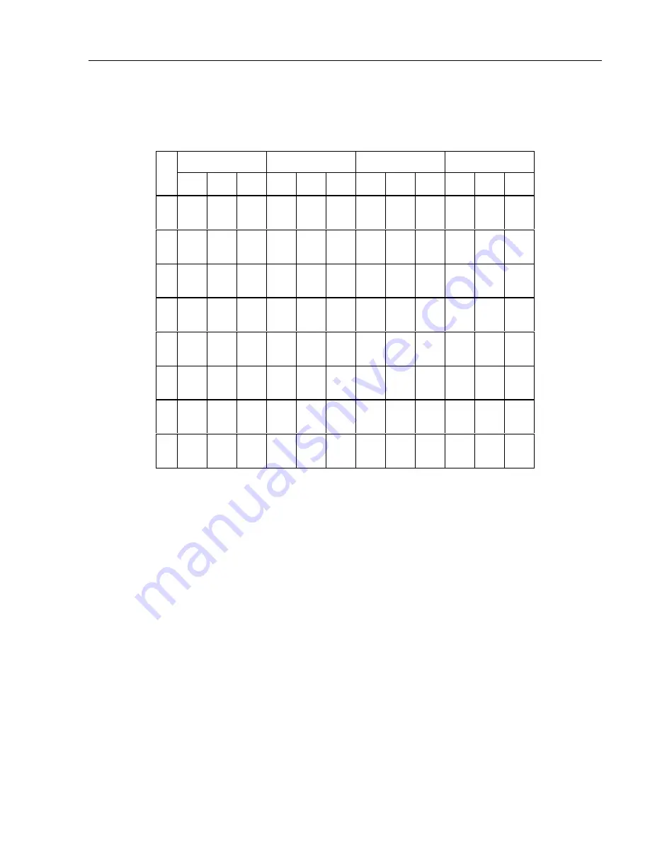
Timing specification
Binary/multibit output timing is as follows.
Unit : ns
800 ns *3
400 ns *4
200 ns *4
100 ns *5
MIN.
TYP.
MAX.
MIN.
TYP.
MAX.
MIN.
TYP.
MAX.
MIN.
TYP.
MAX.
t1
750
800
850
*1
350
400
450
150
200
250
*1
50
100
150
*1
t2
350
400
450
150
200
250
50
100
150
0
50
100
t3
350
400
450
150
200
250
50
100
150
0
50
100
t4
350
400
450
*1
150
200
250
*1
50
100
150
*1
0
50
100
*1
t5
250
300
350
250
300
350
250
300
350
250
300
350
t6
650
700
750
450
500
350
350
400
450
300
350
400
t7
2600
*2
2600
*2
2600
*2
2600
*2
t8
2600
2700
2800
2600
2700
2800
2600
2700
2800
2600
2700
2800
*1
Sometimes these values become several µs longer, due to the memory control.
*2
Sometimes these values become several ms longer, due to the scanner control.
*3
800 ns or 400 ns is the transfer rate specified by the Extended control register #2.
When the output resolution is 400 dpi or less, the front-side data transfer rate is 800 ns.
When the output resolution is 401 dpi or more, the front-side data transfer rate is 400 ns.
*4
These are the transfer rate specified by the Extended control register #2 for back-side reading.
*5
When reading with grayscale output, transfer rate is 100 ns.
Summary of Contents for M3097DE
Page 1: ...C150 E102 01EN M3097DE Image Scanner OEM Manual...
Page 2: ......
Page 4: ...This page is intentionally left blank...
Page 42: ...3 3 Optional image function 3 21...
Page 43: ...Image Functions 3 22 The conceptual image processing flow in the IPC mode is shown below...
Page 45: ...Image Functions 3 24...
Page 70: ...5 3 Cleaning 5 15 Two rollers are included Figure 5 5 Pick roller...
Page 73: ...6 3 Figure 6 1 Jam clearance...
Page 197: ...Scanner Interface Appendix A 124 5 Dimensions of the board For M3093EX DE and M3097DE...


