background image


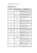
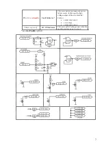
INTERFACE: 

MOLEX 0901301120


PIN (color) 

DESIGNATION 

DESCRIPTION 

1 (-) 

TEMP Test point 

Module’s internal temperature test point. 
By default the pin is unconnected, but can 
be activated on request. 

2,4,5,6 (black) 

Ground


PINS 2,4,5,6 are connected to the circuit 
ground of all internal circuits. The return 
signal connection for all interface signals 
should be made to one of these pins.


3 (

yellow

Voltage Program 

A positive DC voltage applied to this pin 
controls the output voltage set point. 

0-10V corresponds to 0-V

MAX


7 (

blue

INHIBIT 

The high voltage output is inhibited or 
enabled by this pin. 

0V – enabled; 5V or free-standing – 
inhibited.


8 (

green

Ready Indicator 

This pin is pulled to the ground, when the 
output voltage is equal to the program 
voltage (or higher than the program 
voltage).


9, 10 (

red

+15 V 

These pins p15V DC that may be 
used for status LEDs etc. 

Maximum output current 40mA.


11 (

orange

+5 V 

This pin pr5V DC that may be 
used for status LEDs etc. 

Maximum output current 40mA.


12, 18 

N/C


13 (

white

; black 

mark) 

Overtemp 

This pin is pulled to ground when internal 
temperature exceeds approx. 

85°C level

In this case the high voltage output will 
be also disabled.


14 (

white

blue 

mark

Overvoltage 

This pin is pulled to the ground when 
overvoltage occurs. 

In case of 

overvoltage, the high voltage output will 
be also disabled.


15 (

green / 

brown

End of Charge 

Indicator 

PIN15 is pulled to 

ground

 when the 

output voltage is below the program 
voltage.  

Otherwise PIN15 is pulled to +15V. 

16 (

blue / 

white

Secondary Inhibit 

The HV OUTPUT is inhibited (when 
+15V is applied) or enabled (when 0V is 
applied or the pin is free-standing). This 
pin should be used only to control parallel 
operations of two or more power 
modules. 

17 (

violet

Voltage Monitor 

The voltage at this pin is a signal 
proportional to the instantaneous output. 

0-10V corresponds to 0-V

MAX


Current capability 1,5mA; R

out 

= 1kOhm


Summary of Contents for PCA-10

Page 1: ...g This equipment may be dangerous Please read the entire user manual carefully before using the product Important note Module is sensitive to the reverse polarity applied to the output If you aren t s...

Page 2: ...ION 4 COOLING 4 APPEARANCE 4 CONNECTORS PINS INTERFACE SIGNALS 5 INSTALLATION 8 OPERATIONS 8 FAULTS 8 SPECIFICATIONS 9 DIMENSIONAL DRAWING 11 HOW TO ORDER 12 ENVIRONMENTAL PROTECTION 12 NAME AND ADDRE...

Page 3: ...d to open the device Warning The equipment is not suitable for use in presence of a flammable anesthetic mixture with air or with oxygen or nitrous oxide Explanation of symbols Symbol Description Refe...

Page 4: ...could be choosen from 300V to 1500V at the moment of order Higher output voltages are available upon request By default modules are optimized for partial discharge applications Complete discharge mod...

Page 5: ...may result in increased electromagnetic emission and or decreased electromagnetic immunity of the equipment and correspondingly in improper operation MOUNTING M4 thread x4 Module should be mounted usi...

Page 6: ...or status LEDs etc Maximum output current 40mA 11 orange 5 V This pin provides 5V DC that may be used for status LEDs etc Maximum output current 40mA 12 18 N C 13 white black mark Overtemp This pin is...

Page 7: ...some failure occurs In this case the high voltage output will be also disabled Failures output short circuit overvoltage output open circuit 20 transparent HV ON Indicator This pin is pulled to the gr...

Page 8: ...n working range 0V VMAX by applying a DC voltage to the Voltage Program PIN3 of INTERFACE 3 Apply power to the module wait 2 5s until module starts 4 Enable the high voltage output PIN7 of INTERFACE 5...

Page 9: ...be achieved in regime 70 100 of VMAX rated input voltage 25 C 1000W Nominal output power complete discharge modifications can be achieved in regime 10 100 of VMAX rated input voltage 25 C 1000J s Outp...

Page 10: ...of protections section Protections from open circuit from short circuit from overheating from overvoltage Cooling Forced air build in fan Environment Operation temperature 10 40 C Storage temperature...

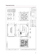
Page 11: ...11 Dimensional drawing...

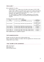
Page 12: ...00V PD 110 240VAC input 1000W 500V output partial discharge IEC 60601 1 2005 A1 2012 IEC 60601 1 2 2014 PCA 10 700V PD 110 240VAC input 1000W 700V output partial discharge On demand PCA 10 1000V PD 11...

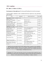
Page 13: ...1000 4 3 List of frequencies Table 9 from 9 V m up to 28 V m PM 18 Hz or 217 Hz FM 1 kHz Complies Immunity from Electrical Fast transient EFT IEC 61000 4 4 2 kV on 230 VAC Tr Th 5 50 ns 100 kHz Compli...

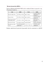
Page 14: ...king voltage depends on modification Input to input opposite polarity before fuses 1x MOOP 340Vpk Output to chassis Output negative is intentionally connected to the chassis Mains part to chassis 1x M...

Reviews: