PF 33 MT - PF 46 MT
Installation and connections
EN - 10
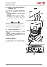
FIG. 3
1
1
4
1
2
3
5
1
5
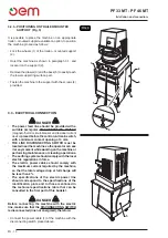
3.2.b - POSITIONING ON TRAILER-MOUNTED
SUPPORT (Fig. 3)
It is possible to place the machine on an appropriate
trailer – mounted support available on option, to position
the machine proceed as follows:
• Lock the wheels (1) of the trailer – mounted support
(2).
• Hoist the machine as shown in paragraph 3.1. and
locate it on the support (2).
• Remove the drawer (3) and the back (5) to easily reach
the lower supporting surface part.
• Fasten the machine to the support with the screws (4)
provided.
3.3 - ELECTRICAL CONNECTION
DANGER
• The power feed line should be provided with a
suitable omnipolar DISCONNECTING SWITCH
(magnetothermic circuit-breaker and residual current
device) placed before the control unit main switch,
with a minimum contact opening of 3 mm.
• THE LINE DISCONNECTING SWITCH must be
located near the machine so the operator can see
it at any moment while working on the machine or
performing maintenance or cleaning operations.
• The earthing system should comply with the local
electric regulations in force.
• The electric power cables should comply with
the maximum current required by the machine,
so that the total voltage drop at full charge will
be less than 2%.
• The specifications of the electric power line
should correspond to the specifications of the
identification plate and to those mentioned in
the technical specifications table that can be
consulted in the first part of this booklet.
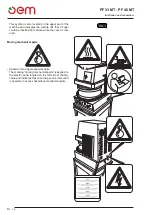
DANGER
Before connecting the machine with the electric
line, make sure that the DISCONNECTING SWITCH
is disconnected (line not energized), therefore:
•
Connect the power cable (1) of the machine with the
disconnecting switch placed above.
Summary of Contents for PF 33 MT
Page 2: ......
Page 4: ......
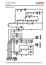
Page 31: ...PF 33 MT PF 46 MT Schema elettrico I 25 SCHEMA ELETTRICO...
Page 32: ...PF 33 MT PF 46 MT Schema elettrico I 26 SCHEMA ELETTRICO MONOFASE...
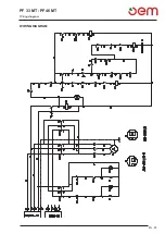
Page 57: ...PF 33 MT PF 46 MT Wiring diagram EN 25 WIRING DIAGRAM...
Page 58: ...PF 33 MT PF 46 MT Wiring diagram EN 26 SINGLE PHASE WIRING DIAGRAM...
Page 83: ...PF 33 MT PF 46 MT F 25 Schema eletrique SCHEMA ELETRIQUE...
Page 84: ...PF 33 MT PF 46 MT F 26 Schema eletrique SCH MA LECTRIQUE MONOPHAS...
Page 109: ...PF 33 MT PF 46 MT D 25 Elektrischer schaltplan Elektrischer schaltplan...
Page 110: ...PF 33 MT PF 46 MT D 26 Elektrischer schaltplan SCHALTPLAN MONOPHASE...
Page 135: ...PF 33 MT PF 46 MT Esquema electrico E 25 ESQUEMA ELECTRICO...
Page 136: ...PF 33 MT PF 46 MT Esquema electrico E 26 ESQUEMA EL CTRICO MONOF SICO...
Page 161: ...PF 33 MT PF 46 MT Esquema el ctricos P 25 ESQUEMA EL CTRICOS...
Page 162: ...PF 33 MT PF 46 MT Esquema el ctricos E 26 ESQUEMA EL CTRICO MONOF SICO...
Page 163: ......


