PF 33 MT - PF 46 MT
Installation and connections
EN - 14
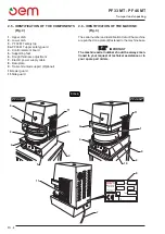
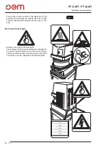
FIG. 1
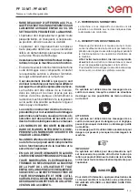
This symbol is also located on the upper part of the
machine and indicates the remote risk that a finger
could be inserted from above while the cover is low-
ered.
Moving mechanical parts
• Hazard of moving mechanical parts.
The marking “moving mechanical parts” is applied on
the electric panel located on the left side of the ma-
chine and indicates that once the panel is removed it
is possible to access hazardous mechanical parts.
Summary of Contents for PF 33 MT
Page 2: ......
Page 4: ......
Page 31: ...PF 33 MT PF 46 MT Schema elettrico I 25 SCHEMA ELETTRICO...
Page 32: ...PF 33 MT PF 46 MT Schema elettrico I 26 SCHEMA ELETTRICO MONOFASE...
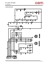
Page 57: ...PF 33 MT PF 46 MT Wiring diagram EN 25 WIRING DIAGRAM...
Page 58: ...PF 33 MT PF 46 MT Wiring diagram EN 26 SINGLE PHASE WIRING DIAGRAM...
Page 83: ...PF 33 MT PF 46 MT F 25 Schema eletrique SCHEMA ELETRIQUE...
Page 84: ...PF 33 MT PF 46 MT F 26 Schema eletrique SCH MA LECTRIQUE MONOPHAS...
Page 109: ...PF 33 MT PF 46 MT D 25 Elektrischer schaltplan Elektrischer schaltplan...
Page 110: ...PF 33 MT PF 46 MT D 26 Elektrischer schaltplan SCHALTPLAN MONOPHASE...
Page 135: ...PF 33 MT PF 46 MT Esquema electrico E 25 ESQUEMA ELECTRICO...
Page 136: ...PF 33 MT PF 46 MT Esquema electrico E 26 ESQUEMA EL CTRICO MONOF SICO...
Page 161: ...PF 33 MT PF 46 MT Esquema el ctricos P 25 ESQUEMA EL CTRICOS...
Page 162: ...PF 33 MT PF 46 MT Esquema el ctricos E 26 ESQUEMA EL CTRICO MONOF SICO...
Page 163: ......


