PF 33 MT - PF 46 MT
EN - 16
Safety devices
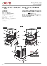
FIG. 3
O
T
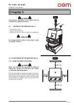
FIG. 4
1
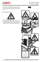
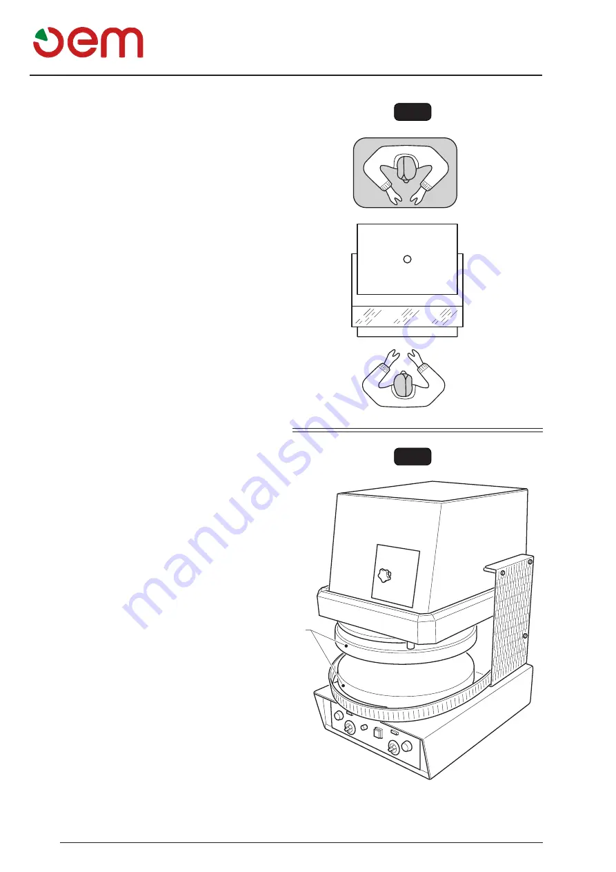
4.4 - OPERATOR AREAS (Fig. 3)
During the machine functioning, the user is in front of it
in order to be able to easily insert the dough ball in the
machine as well as easily remove the pressed dough
disc from the machine; concerning allowed positions see
Fig 3 Positions (O).
For maintenance operations, the user may put himself
on the upper machine part - position (T).
4.5 - RESIDUAL RISK ZONES (Fig. 4)
A residual risk zone is the dish area (1); risk of scalding.
Use appropriate personal protective equipment.
Summary of Contents for PF 33 MT
Page 2: ......
Page 4: ......
Page 31: ...PF 33 MT PF 46 MT Schema elettrico I 25 SCHEMA ELETTRICO...
Page 32: ...PF 33 MT PF 46 MT Schema elettrico I 26 SCHEMA ELETTRICO MONOFASE...
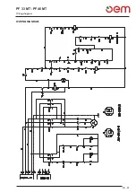
Page 57: ...PF 33 MT PF 46 MT Wiring diagram EN 25 WIRING DIAGRAM...
Page 58: ...PF 33 MT PF 46 MT Wiring diagram EN 26 SINGLE PHASE WIRING DIAGRAM...
Page 83: ...PF 33 MT PF 46 MT F 25 Schema eletrique SCHEMA ELETRIQUE...
Page 84: ...PF 33 MT PF 46 MT F 26 Schema eletrique SCH MA LECTRIQUE MONOPHAS...
Page 109: ...PF 33 MT PF 46 MT D 25 Elektrischer schaltplan Elektrischer schaltplan...
Page 110: ...PF 33 MT PF 46 MT D 26 Elektrischer schaltplan SCHALTPLAN MONOPHASE...
Page 135: ...PF 33 MT PF 46 MT Esquema electrico E 25 ESQUEMA ELECTRICO...
Page 136: ...PF 33 MT PF 46 MT Esquema electrico E 26 ESQUEMA EL CTRICO MONOF SICO...
Page 161: ...PF 33 MT PF 46 MT Esquema el ctricos P 25 ESQUEMA EL CTRICOS...
Page 162: ...PF 33 MT PF 46 MT Esquema el ctricos E 26 ESQUEMA EL CTRICO MONOF SICO...
Page 163: ......


