background image

5

O W N E R ’ S   M A N U A L

PS-12

C O N N E C T I O N

No signal connection cable is provided with the PS-12 subwoofer since the type and length of cable is installation 

specific.  A shielded RCA type coaxial cable, a shielded two-conductor wire with RCA type connectors, or a 


2-channel speaker cable is required for connection of the PS-12 to the audio system.  Ensure sufficient length to 

reach from the system source to the subwoofer’s line or speaker level input.  If you are uncertain about the type 

and length of wire to purchase after reading this section and the section on Placement then please contact your 

dealer for assistance.  

Before making any connections, ensure that power cord is disconnected or that the main power switch is switched 

to the off position.  

Input Signal:  Follow the diagram on page 7 for connecting the subwoofer to your audio system.  Use the option 

that best suits your installation.  

WARNING: Use only one of the three options,

 (Do Not Combine Options).  

The information below will aid in determining which option to use.  

Note: The best performance can be achieved using the line level inputs (                or                 ) as opposed to 

the speaker level inputs (                ).  

!     

RISQUE DE CHOC ELETRIQUE 

NE PAS OUVRIR

1
2

3

4

5

6

7

8

9

10

1
2
3
4
5
6
7
8
9

10

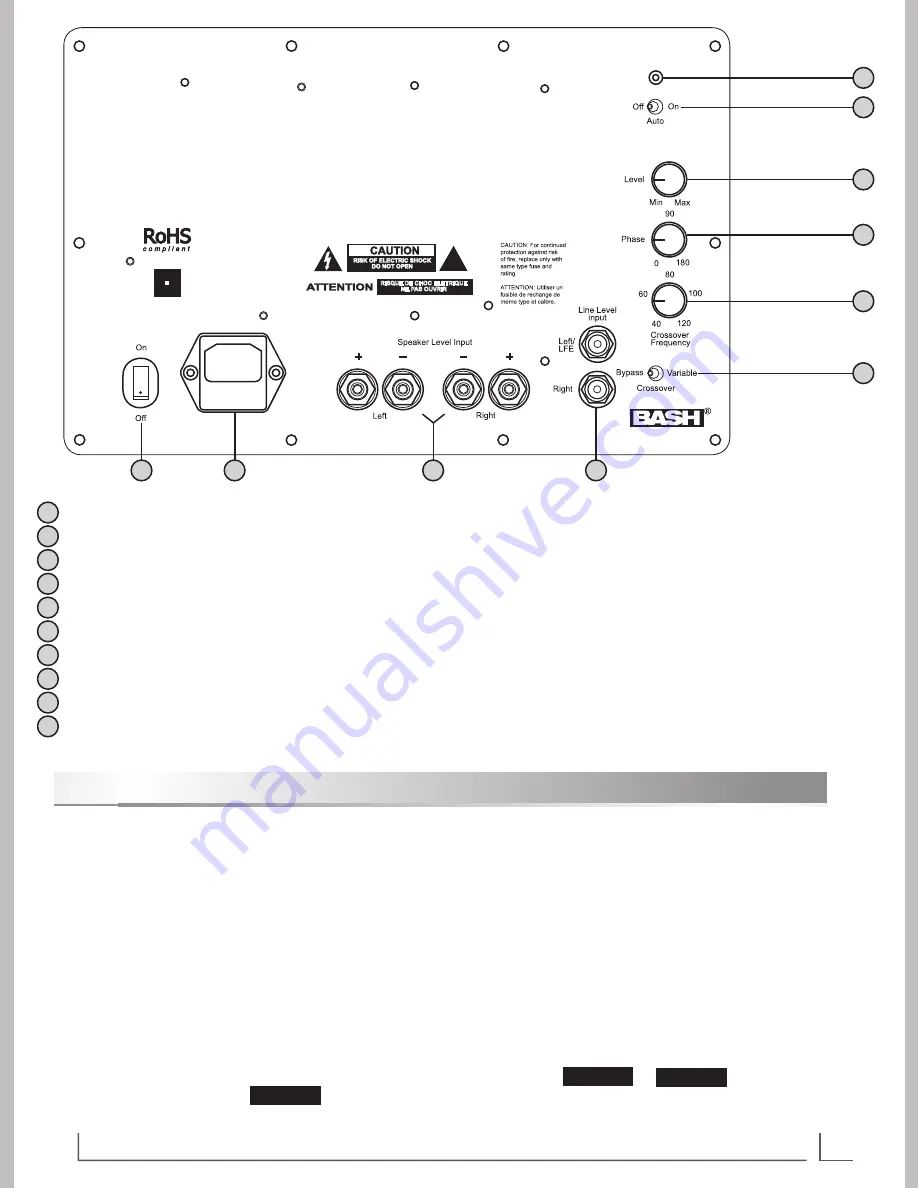
Power and Standby Mode Indicator

 – Off=No Power; Green=On; Red=Standby

Auto Power Mode Switch 

– Selects if amplifier power is signal activated; On=Signal Sensing, Off=Bypassed (Amp ON)

Level Control

 – Adjusts output level of subwoofer

Phase Control

 – Adjusts relative alignment of output signal with respect to the input; 0°=In Phase, 180°=Out of Phase

Crossover Frequency Control 

– Adjusts low pass filter cutoff frequency

Crossover Bypass Switch

 – Selects if internal crossover (low pass filter) is active; Variable=Active, Bypass=Inactive

Line Level Input

 – Input connection for RCA Line Level signals from processor or preamp; Includes LFE & Sub signals

Speaker Level Input

 – Input connection for High Level signals from amplifier

Power Input Receptacle and Fuse Holder 

– IEC 2-conductor 120V receptacle accepts supplied IEC power cord

Master (Main) Power Switch 

– Primary power; On=Power Enabled; OFF=Power disconnected from amplifier circuit

OPTION 2

OPTION 3

OPTION 1

U.S. Patent #5,075,634 and  

5,510,753 Patent Pending

Summary of Contents for PS-12

Page 1: ...300 Watt Powered Subwoofer 12 E X T R A L O N G T H R O W Heavy Duty Woofer F R E E S T A N D I N G P O W E R E D S U B W O O F E R PS 12 OWNERS MANUAL...

Page 2: ...m being walked on or pinched particularly at plugs convenience receptacles and the point where they exit from the apparatus Only use attachments accessories specified by the manufacturer Unplug this a...

Page 3: ...n developed to provide you with pleasing accurate bass in your music system or home theater sound system This manual covers operating procedures general setup and technical specifications for your PS...

Page 4: ...t either pattern Front of Subwoofer Front of Subwoofer Bottom of Subwoofer Showing 4 Rubber Feet Bottom of Subwoofer Showing 4 Spiked Feet Front of Subwoofer Front of Subwoofer Bottom of Subwoofer Sho...

Page 5: ...mining which option to use Note The best performance can be achieved using the line level inputs or as opposed to the speaker level inputs RISQUE DE CHOC ELETRIQUE NE PAS OUVRIR 1 2 3 4 5 6 7 8 9 10 1...

Page 6: ...ctions are parallel and you may use the B output for the subwoofer If the A speakers discontinue playing when the B button is engaged then you will need to connect the subwoofer in parallel to the A s...

Page 7: ...75 UNBAL REMOTE OUT AC OUTLETS AUDIO VIDEO S VIDEO DVD VCR IN OUT VIDEO FRONT A R L L R FRONT SURROUND SUR BACK SUB WOOFER PRE OUT SINGLE CENTER Left Speaker Level Input Right Right Left LFE Line Lev...

Page 8: ...ne should contact an expert in the field of acoustics if one finds that the low frequency reproduction in their room is unsatisfactory Placing the subwoofer near a wall will substantially increase its...

Page 9: ...ystem speakers We have found that most speakers with 6 to 8 woofers blend well with the crossover set somewhere between 50Hz and 80Hz Readjust the Level and the Frequency controls up or down as necess...

Page 10: ...508D mm Shipping Weight 51lbs 23 2kg Fine Tuning the Controls Crossover Switch If you choose to bypass the internal crossover and use an external crossover such as those located in most modern receive...

Page 11: ...11 O W N E R S M A N U A L PS 12 N O T E S...

Page 12: ...OEM SYSTEMS COMPANY Sparks Nevada 775 355 0405 800 291 0561 FAX www oemsystems com info oemsystems com Rev F...

Reviews: