29 - 97
Instruction Manual
AC 02/2019-rev.1.1
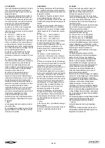
4.3 ACCOPPIAMENTI CON INGRANAGGI O
RIDUTTORI
Vedi paragrafo 4.1 (accoppiamento diretto) ed
eventuali informazioni fornite dal costruttore del
riduttore. Per questa applicazione è consigliato
richiedere l’esecuzione della flangia motore con
grado di precis
ione aumentato “extra
-
precisa” per
contenere gli errori e i disallineamenti.
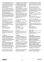
4.3 COUPLINGS WITH GEARS OR WITH
GEARBOX
See paragraph 4.1 (direct coupling) and any
information supplied by the gear reduction box
manufacturer. For this application, it is advisable
to request the manufacturing of the motor flange
with the “extra
-
sharp” pre
cision execution to
contain the errors and misalignments.
4.3 ANTRIEBE MIT ZAHNRÄDERN ODER
GETRIEBEN
Siehe Abschnitt 4.1 (direkter Anbau) und eventuell
vom Hersteller des Untersetzungsgetriebes
gelieferte Informationen. Für diese Anwendung wird
geraten, die Ausführung des Motorflansches mit
einem erhöhter Plan- und Rundlaufgenauigkeit zu
bestellen, damit Flichtungsfehler zu beschränken.
4.3.1 ACCOPPIAMENTO DEL MOTORE AL
RIDUTTORE MEDIANTE INNESTO DIRETTO
(RIDUTTORE AD ALBERO CAVO SENZA
GIUNTO FLESSIBILE).
4.3.1 ASSEMBLY OF THE MOTOR ON THE
GEARBOX WITH DIRECT CONNECTION
(GEARBOX WITH HOLLOW SHAFT WITHOUT
FLEXIBLE COUPLING).
4.3.1 DIREKTER MOTORANBAU AN DAS
GETRIEBE (GETRIEBE MIT HOHLWELLE OHNE
FLEXIBLE KUPPLUNG)
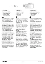
Per effettuare un corretto assemblaggio del
motore sul riduttore è assolutamente
indispensabile effettuare un esatto allineamento
fra albero motore, albero cavo del riduttore e fra
le due flange di accoppiamento.
Eventuali vibrazioni ed irregolarità di rotazione
sono indizio di allineamenti imprecisi che
causano anomalie di funzionamento e rottura
dell’albero motore.
Consultare anche il paragrafo
3.8.1 relativo alle posizioni di montaggio
raccomandate ed in particolare al montaggio in
forma B5 + supporto (paragrafo 4.3.2)
In order to carry-out a correct assembly of the
motor on the gearbox it is absolutely necessary
to make a precise alignment between the motor
shaft and the gearbox hollow shaft and between
the two flanges.
Any vibrations or irregular rotations are
indications of inaccurate alignments which will
cause operating malfunctions and the breakage
of the motor shaft.
Check also the paragraph 3.8.1 relative to the
raccomanded mountig positions and in details to
the B5 + support mounting (paragraph 4.3.2)
Um eine korrekte Montage des Motors auf dem
Getriebe aus zu führen ist unbedingt notwendig eine
genaue Ausrichtung zwischen Motorwelle und
Getriebehohlwelle sowie den 2 Anschlussflanschen
zu erreichen.
Vibrationen oder schwankende Drehzahlen zeigen
Fluchtungfehler an, die Funktionstörungen und
Wellenbrüche verursachen.
Auch den Abschnitt 3.8.1 über die empfohlenen
Montagepositionen konsultieren, besonders die
Montagepostion B5 + Unterstützung
(Abschnitt
4.3.2)
1
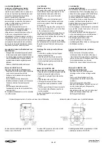
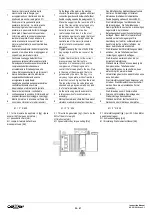
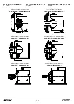
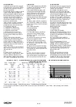
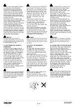
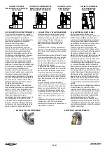
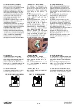
Posizionare il riduttore con l’albero cavo di
accoppiamento al motore (albero veloce)
rivolto verso l’alto. Il riduttore non deve
essere collegato a nessun carico e l’albero
lento deve essere libero di ruotare.
1
Place the gearbox with the hollow shaft that
has to be connected with the motor (input
shaft) facing up. The gearbox has to be
without load and the low speed shaft has to
be free to rotate.
1
Das Getriebe mit der Eintriebshohlwelle nach
oben aufstellen. Das Getriebe darf an keine
Last gekoppelt sein und die Abtriebswelle
muss frei rotieren können.
2
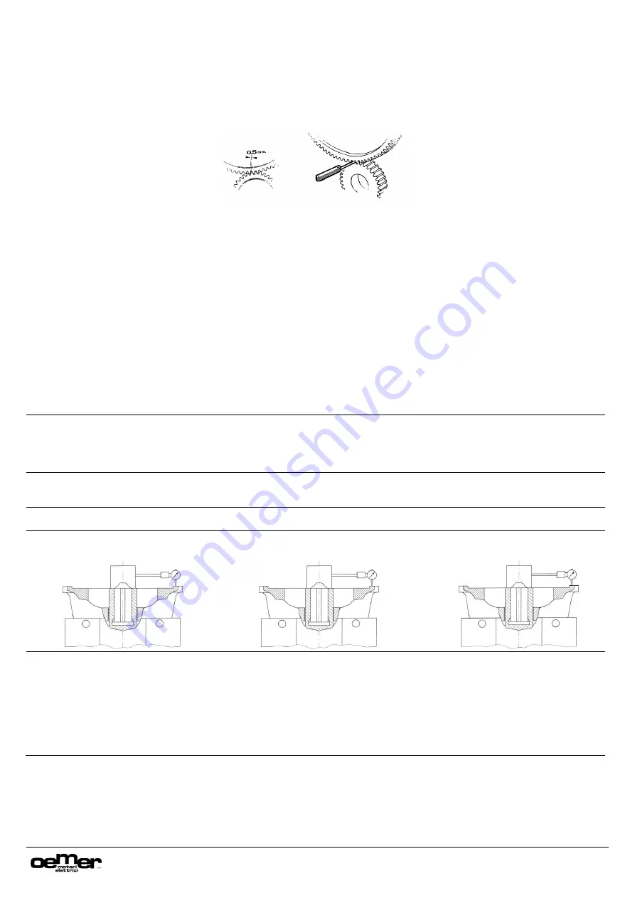
Controllare la perpendicolarità e la concentricità
della flangia del riduttore rispetto all’albero cavo
mediante un comparatore meccanico.
2
Check the perpendicularity and the
concentricity of the gearbox flange respect to
the hollow shaft with a mechanical gauge.
2
Mittels einer Messuhr die senkrechte
Fluchtung und den Rundlauf der Hohlwelle
zum Getriebeflansch kontrollieren.
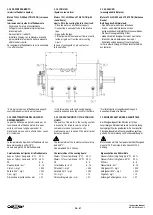
3
Fissare la base magnetica del comparatore
sull’albero c
avo del riduttore.
3
Fix the magnetic support of the mechanical
gauge on the gearbox hollow shaft
3
Den magnetischen Sockel der Messuhr auf
der Hohlwelle befestigen
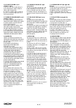
4
Appoggiare il tastatore del comparatore sul
piano della flangia del riduttore.
4
Place the head of the mechanical gauge on
the surface of the gearbox flange
4
Den Tastkopf der Messuhr auf dem
Getriebeflansch aufsetzten
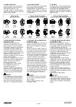
5
Fare ruotare molto lentamente l’albero del
riduttore (se possibile agendo sull’albero
lento) e verificare che la flangia sia
perfettamente perpendicolare rispetto
all’albero del riduttore. Con
la rotazione
completa di 360° l’errore massimo
ammesso è di 0.05mm. Contrassegnare la
flangia con un pennarello indicando i due
punti (massimo e minimo) misurati.
5
Turn slowly the gearbox shaft (if possible
rotating manually the output shaft) and
check that flange flatness that must be
perfectly perpendicular respect to the
gearbox shaft. With a complete rotation of
360° the max. admissible error is
0.05mm. Write with a marker on the
flange surface the two points checked
(max. and. Min.).
5
Die Getriebewelle langsam drehen (falls
möglich die Abgangswelle per Hand drehen)
und prüfen, ob der Flansch perfekt
rechtwinklig zur Getriebewelle steht. Die
maximal zugelassene Abweichung für eine
komplette 360° Drehung beträgt 0.05mm. Auf
dem Flansch die beiden Messpunkte
(Minimum und Maximum) mit einem Filzstift
anzeichnen.

