31 - 97
Instruction Manual
AC 02/2019-rev.1.1
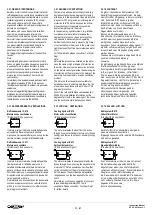
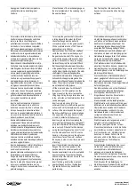
16
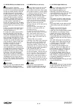
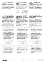
Alimentare il motore e farlo ruotare (se
possibile a bassa velocità). Durante questa
fase il riduttore potrebbe essere senza
lubrificante. Limitare la prova a qualche minuto.
16
Supply the motor and operate it (if possible
at low speed). During this operation the
gearbox could be without lubricant. Limit
this test to few minutes.
16
Den Motor anschließen und drehen lassen
(möglichst mit kleiner Drehzahl). In dieser Phase
könnte das Getriebe ohne Schmiermittel laufen.
Diesen Test auf einige Minuten begrenzen.
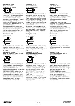
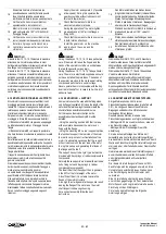
17
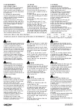
Verificare che non ci siano vibrazioni,
spostamenti e/o rumori anomali.
17
Check that there are not vibrations,
muvments or abnormal noise.
17
Prüfen, dass keine Vibrationen, Bewegungen
oder anormale Geräusche vorliegen.
18
Mentre il motore è in rotazione serrare
gradualmente ed a 180° tutti i bulloni di
fissaggio flangia.
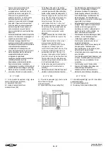
18
During the operation of the motor tighten
gruadually and at 180° all the flanges
fixing bolts.
18
Während dem der Motor dreht die Schrauben
graduell und jeweils um 180° versetzt
anziehen.
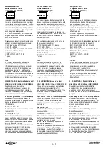
19
Verificare che non ci siano vibrazioni e/o
rumori anomali nei due sensi di rotazione.
19
Check that there are not vibrations or noise
in both rotation directions.
19
Prüfen, dass in beiden Laufrichtungen keine
Vibrationen oder anormale Geräusche vorliegen.
20
Installare il gruppo sulla macchina e
controllare nuovamente i rumori e le
vibrazioni.
20
Install the gearmotor on the machine
and re-check the noise and the
vibrations.
20
Den Getriebemotor auf der Maschine
installieren und wieder auf Geräusche oder
Vibrationen prüfen.
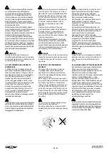
PERICOLO
Durante le fasi 12, 13, 14, 15 prestare la massima
attenzione. Se il motore cade le dita e le mani
dell’operatore potrebbero rimanere sc
hiacciate tra le
due flange con conseguenze gravissime.
Durante le fasi 16, 17, 18, 19 prestare la massima
attenzione. Il motore è alimentato elettricamente e
potrebbe non avere le protezioni montate. Le mani
dell’operatore si trovano vicine agli organi me
ccanici
in rotazione e sotto tensione. Non fare mai ruotare il
motore disaccoppiato con la chiavetta innestata
nell’albero o nel caso assicurarla con abbondante
nastro adesivo.
DANGER
During the phases 12, 13, 14, 15 take particulare
care. If the motor fall down the fingers and the
hands of the operator could be crunch between
the two flanges with serious injury.
During the phases 16, 17, 18, 19 Take particular
care. The motor is electrically supplied and could
not have installed the protections. The hands of
the operator are close to the mechanical rotating
components parts that are under voltage.
Never operate the motor uncoupled with the key
inserted in the shaft, or in case lock it with a lot of
adhesive tape.
GEFAHR
Während der Schritte 12,13,14 und 15 besondere
Vorsicht walten lassen. Wenn der Motor runterfällt
könnten Hände und Finger des Monteurs eingequetscht
werden mit schwerwiegenden Folgen.
Während der Schritte 16, 17,18 und 19 besondere
Vorsicht walten lassen. Der Motor ist
spannungsversorgt und die Schutz-einrichtungen
könnten demontiert sein. Die Hände des Monteurs
befinden sich in der Nähe rotierender und unter
Spannung stehender Teile. Niemals den Motor
entkoppelt und mit Passfeder im Sitz laufen lassen oder
zumindest mit ausreichend Klebeband sichern.
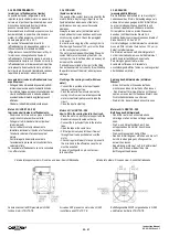
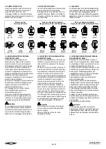
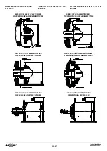
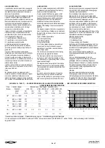
4.3.2 MONTAGGIO IN FORMA B5 + SUPPORTO
Alcuni motori non possono essere utilizzati con il
montaggio realizzato tramite la sola flangia (vedi
tabelle 3.8.1) in quanto la lunghezza del motore ed il
relativo peso possono causare flessioni della
struttura ed innescare vibrazioni e/o risonanze.
Per questo motivo, i motori che non permettono il
montaggio in forma B5, devono essere installati:
- Utilizzando la forma B35 che prevede un appoggio
su tutta la base del ll fissaggio tramite
flangia.
- Utilizzando la forma B5 + un supporto posteriore
che ha la funzione di sostenere la parte non vincolata
del motore.
Per effettuare una corretta installazione del motore è
assolutamente indispensabile evitare che il supporto
carichi eccessivamente la parte posteriore del motore
forzandolo verso l’alto e creando la flessione
della
flangia e dell’albero.
Il supporto non deve essere di tipo rigido ma deve
essere provvisto di molle a tazza o supporti in
gomma comprimibili.
Normalmente questi supporti sono realizzati tramite
bulloni ben dimensionati, controdadi di fissaggio e
molle a tazza (o antivibranti in gomma).
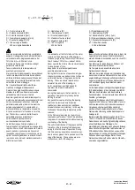
La spinta ideale che il supporto deve esercitare è
quantificabile al 50% del peso totale del motore.
Una spinta inferiore non è in grado di evitare la
flessione della struttura. Una spinta superiore causa
l’effetto op
posto caricando la flangia del motore e
disallineando l’albero rispetto alle sedi dei cusicnetti.
Per un corretto montaggio seguire le seguenti
istruzioni.
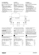
4.3.2 B5 MOUNTING + SUPPORT
Some motors can not be used with the fixing made
only by flange (see table 3.8.1) since the length of the
motor and the relative weight can determinate the
structure flexion and vibrations and/or noise.
For this reason, the motors that can not be
assembled on the machine only B5, must be
installed:
- Using the mounting position B35 that is made
with a complete base under the motor and +
fixing with the flange.
- Using the mounting B5 + a rear support that has
the function to support the rear side of the motor
In order to carry-out a correct installation of the
motor it is absolutely necessary that the support
will not load too much the rear side of the motor
forcing this part up and generating the flexion of
the flange and the shaft.
The support has not to be rigid type but must be
provided with tray springs or rubber compressible
components.
Normally these supports are made with well sized
bolts, fixing nuts and tray springs (or rubber
compressable components)
The ideal thrust that the support has to generate
is the 50% of the total weight of the motor.
A Insufficient thrust it is not able to avaid the
flexion of the motor structure
A too high thrust will generate the opposite result
loading the flange of the motor and the motor
shaft respect the bearings housing.
For a correct assembly follow the next
instructions.
4.3.2 B5 MONTAGE MIT UNTERSTÜTZUNG
Einige Motoren können nicht in reiner
Flanschmontage betrieben werden (siehe Tabelle
3.8.1), da Länge und Gewicht des Motors zu
Biegungen und dadurch zu Vibrationen oder
Geräuschen führen können.
Deshalb müssen Motoren, die keine reine
Flanschmontage erlauben wie folgt montiert werden:
- Montage in B35, die sowohl eine Fuss- als auch
eine Flanschmontage vorsieht.
- Montage in B5 mit rückseitiger Gewichts-
abstützung.
Für eine korrekte Montage des Motors darf
keinesfalls eine zu starke Unterstützung erfolgen,
die den Motor über die Horizontale drückt und damit
Welle und Flansch verbiegt.Die Unterstützung muss
starr sein, aber über Tellerfedern oder Gummipuffer
verfügen.
Normalerweise werden diese Unterstützungen mit
ausreichend dimensionierten Schrauben, Muttern
und vibrationsdämpfenden Gummipuffern
ausgeführt.
Die ideale Unterstützungskraft kann mit 50%
des Motorgewichtes angegeben werden. Eine
Unterstützung unterhalb dieses Wertes kann
eine Durchbiegung der Motorstruktur nicht
vermeiden.
Eine Unterstützung oberhalb dieses Wertes
erreicht den gegenteiligen Effekt, belastet den
Motorflansch und bringt die Motorwelle aus der
Fluchtung mit den Wälzlagern.
Für eine korrekte Montage die folgende
Anleitung befolgen.

