32 - 97
Instruction Manual
AC 02/2019-rev.1.1
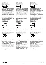
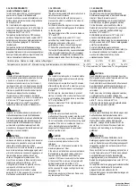
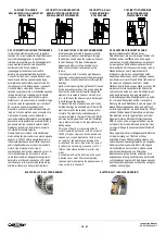
1
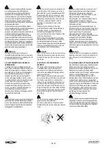
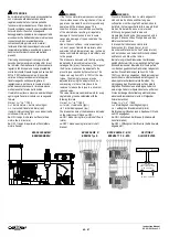
Fissare il motore alla struttura della
macchina tramite la flangia. (per
accoppiamenti con riduttore ad innesto
diretto vedere anche il paragrafo 4.3.1).
1
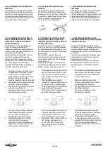
Fix the flange of the motor on the machine
structure. (for assembly on gearbox with direct
connection (gearbox with hollow shaft without
flexible coupling see also the paragraph 4.3.1).
1
Den Motorflansch an die Maschinen-aufnahme
montieren. Für die Montage mit direktem
Motoranbau (Getriebe mit Hohlwelle ohne
flexible Kupplung siehe auch Abschnitt 4.3.1.
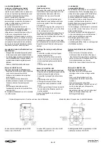
2
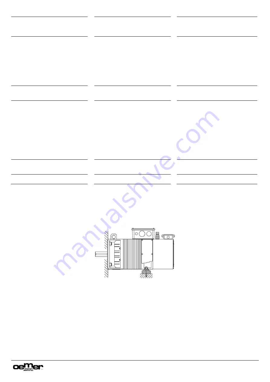
Posizionare il supporto nella parte
posteriore del motore. Le molle a tazza
devono spingere solo sul coperchio
posteriore in prossimità dei fori di fissaggio
(zona piedi). Questo punto presenta dei
rinforzi e quindi è la zona più indicata per
realizzare la spinta. Non posizionare le
molle a tazza nella zona centrale del
motore (sullo statore) in quanto potrebbero
deformarlo.
2
Place the support on the rear side of the
motor, The tray springs must push only
on the rear-cover close to the fixing
holes (feet area). This area has
reinforced parts and so it is the most
indicated zone where to apply the thrust.
Do not place the tray springs under the
central area of the motor (laminated
stator) since this component can be
damaged.
2
Die Unterstützung auf der Rückseite des
Motors anbringen. Die Tellerfedern oder
Gummipuffer dürfen nur auf dem rückseitigen
Lagerschild in der Nähe der
Befestigungsbohrungen (Fussbefestigung)
aufliegen. Dieser Bereich ist verstärkt und
deshalb zur Aufnahme geeignet. Die
Abstützung darf nicht im mittleren Bereich
des Motors (auf dem Stator) erfolgen, da
dieser deformiert werden könnten.
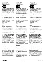
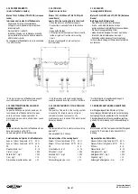
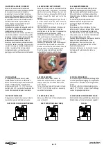
3
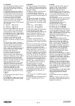
Avvitare manualmente i bulloni di spinta fino
a quando le molle a tazza si appoggiano al
coperchio posteriore del motore.
3
Tighten manually the thrust bolts tll the
tray springs touch the rear cover of the
motor.
3
Die Schrauben der Unterstützung von Hand
anziehen, bis die Tellerfedern auf dem
rückseitigen Lagerschild aufliegen.
4
Continuare il serraggio dei bulloni fino a
quando non sarà esercitata la spinta corretta.
Durante questa fase è necessario controllare la
compressione delle molle e dosare
accuratamente la forza da applicare alla
chiave. Dato il passo della vite e la forza che il
braccio della chiave esercita, è facilissimo
superare abbondantemente e senza
accorgersene la spinta ideale.
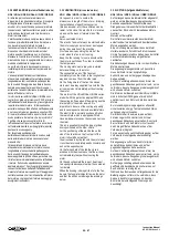
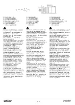
La spinta da esercitare può essere calcolata e
controllata utilizzando una chiave
dinamometrica e la formula sotto riportata.
4
Tighten the thrust bolts till the correct
pressure is applied. During this
operation it is necessary to check the
compression of the springs and to
controll the force applied to the key. Due
to the step of the screw and the force
gerenared by the arm of the key, it is
very easy to generate, without realize, a
thrust that is much higher than the ideal.
The ideal thurst can be calculated and
checked using a dynamometric key and
the formula indicated below.
4
Die Schrauben weiter anziehen, bis zur
korrekten Unterstützung.
Während dieser Phase ist es notwendig die
Kompression der Tellerfedern oder
Gummipuffer genau zu kontrollieren, da es
einfach möglich wäre die ideale
Unterstützung deutlich zu überschreiten ohne
es zu bemerken.
Die Unterstützungskraft kann berechnet und
mit einem Drehmomentschlüssel kontrolliert
werden. Dazu die untenstehende Formel
verwenden.
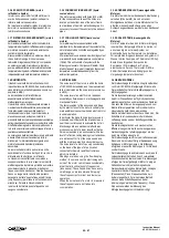
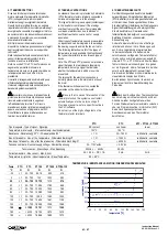
5
Fissare i bulloni tramite i controdadi e
contrassegnare la posizione di riferimento per
eventuali successivi smontaggi e rimontaggi.
5
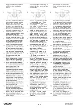
Fix the bolts using a nurts and mark the
reference position for eventual oter re-
assembly.
5
Die Schrauben nun mit Kontermuttern
fixieren und für spätere Demontage oder
Wiedermontage kennzeichnen
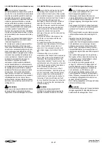
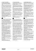
6
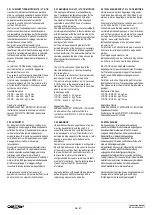
Mentre il motore è in rotazione, verificare che
non ci siano vibrazioni e/o rumori anomali.
6
Start-up the motor and check that there are not
vibrations or abnormal noise from the motor.
6
Während der Motor läuft auf anormale
Geräusche oder Vibrationen überprüfen.
M = F * h / 628
F = forza di spinta da applicare in [kg]
–
(deve
essere il 50% del peso del motore).
H = passo della vite in [mm]
M = coppia di taratura della chiave
dinamometrica in [Nm]
M = F * h / 628
F = Thrust to be generated [kg]
–
(has to be the
50% of the motor weight).
H = Bolts step [mm]
M = Dynamometric key torque setting [Nm]
M = F * h / 628
F = Unterstützungskraft [kg]
–
(soll 50% des Motor-
gewichtes betragen).
H = Schraubensteigung [mm]
M = Einstellung Drehmomentschlüssel [Nm]

