41 - 97
Instruction Manual
AC 02/2019-rev.1.1
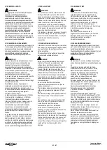
5.1 TERMOPROTETTORI
Di serie è fornita la protezione termica del
motore mediante 3 termoprotettori bimetallici
(PTO) collegati in serie ed incorporati
direttamente negli avvolgimenti del motore.
Questo tipo di protettore fornisce un segnale
(apertura del contatto) di sovratemperatura degli
avvolgimenti e consente di proteggere il motore
da sovraccarichi o funzionamenti anomali dovuti
a mancanza di ventilazione, sovracorrente,
anomalie di alimentazione.
Altri tipi di sensori di temperatura sono
disponibili a richiesta e possono essere integrati
negli avvolgimenti ed anche nei supporti dei
cuscinetti.
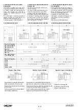
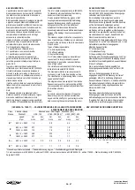
Nella tabella sottostante sono elencati i tipi di
sensori di temperatura disponibili, la loro
funzione e le curve caratteristiche.
Note: Le sonde PTO e PTC non forniscono un
segnale che permette di misurare la
temperatura ma solo un segnale che indica se
la temperatura è entro od oltre il limite
prestabilito.
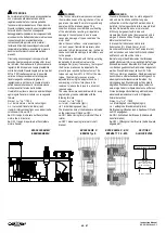
Il morsetto di collegamento è normalmente posto
all’interno della scatola morsetti principale
.
Il mancato collegamento delle sonde termiche fa
decadere la garanzia sul prodotto.
Accertarsi che in caso di intervento della
protezione termica l’impianto non possa essere
riavviato automaticamente in seguito al
raffreddamento del motore. Per il riavvio
prevedere un relè da ripristinare manualmente
oppure una routine nel programma del PLC.
Non effettuare la prova di alta tensione sui
terminali dei protettori termici.
5.1THERMAL PROTECTIONS
As standard, the motor is protected by 3 bimetallic
(PTO) thermal protectors, internally connected in
series and incorporated into the windings.
This type of protector gives a signal (contact open)
to the inverter or control panel if the windings
overheat, to protect the motor from prolungated
overloads or malfunctions due to blocked or
insufficient ventilation, overcurrent, or supply
anomalies.
Other types of temperature sensors are available
on request and can be integrated in the windings,
the bearing supports and into the fan unit motor..
The following table shows a list of the types of
temperature sensors available, their function and
the typical characteristic curves for each type of
device..
Note: The PTO and PTC probes do not provide a
signal that gives the real measure theworking
temperature, but only a signal that indicates
whether the temperature is within or over the
preset limit.
The terminal for the electrical connection is
normally placed inside the main terminal box of
the motor.
If the thermal switches are not connected the
guarantee on the product will be invalid.
Be sure that, in case of intervention of the
thermal protection, the system cannot restart
automatically due to the motor cooling off.
Provide a manual re-set or a specific routine in
the PLC software.
Do not carry out the high voltage test on the
thermal protector terminals
5.1 ÜBERHITZUNGSSCHUTZ
Der Überhitzungsschutz des Motors besteht
serienmäßig aus 3 bimetallischen Elementen
(PTO-Kaltleiter), die in Reihe geschaltet sind und
sich direkt in den Wicklungen befinden. Diese
Schutzart gibt bei Überhitzung der Wicklungen ein
Signal (Kontaktöffnung) ab und ermöglicht den
Schutz des Motors vor Überlasten oder
fehlerhaftem Betrieb aufgrund von mangelnder
Belüftung, Überstrom und anomaler
Stromversorgung.
Andere Temperaturfühler sind auf Anfrage
lieferbar und können in die Wicklungen und
auch in die Lagerböcke integriert werden.
In der nachstehenden Tabelle sind die
verschiedenen verfügbaren Temperaturfühler,
ihre Funktion und ihre Kennkurven angeführt.
Hinweis: PTO- u. PTC-Fühler sind keine Mess-
fühler mit kontinuierlichem Signal. Sie geben
nur ein Signal ab, ob die Temperatur über oder
unter dem festgelegten Grenzwert liegt.
Die Klemmen befinden sich normalerweise im
Hauptklemmenkasten des Motors.
Bei fehlendem Anschluss der thermischen
Elemente erlischt die Gewährleistung des
Produktes.
Nach dem Auslösen der Thermikschutzes
kann die Anlage nicht automatisch nach dem
Abkühlen wieder hochgefahren werden.
Für den Wiederanlauf ein Handrelais vorsehen
oder ein Programmroutine im Umrichter (PLC)
Keine Hochspannungstests an den
Anschlussklemmen des Thermofühler
durchführen.
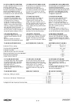
PTO
PTC
KTY
–
PT100
–
PT1000
Tipo di segnale -
Type of signal -
Signaltyp
NC contact.
non linear
l
inear
Temperatura di intervento -
Intervention temp.-
Auslösetemperatur
150 °C
150 °C.
-
Resistenza -
Resistance @ 20°C
–
Wiederstand bei 20°
< 1 Ω
20 ÷ 750 Ω
vedi tabella
- see table
Res. All’intervento –
Res. at the temperature -
Widerstand Bei Eingriff
< 1 Ω
1300
Ω
vedi tabella
- see table
Res. dopo l’intervento –
Res. after the intervention -
Widerstand Nach Eingriff
4000 Ω
vedi tabella
- see table
Tensione nominale -
Nominal supply voltage
–
Nominal Spannung
24…110Vac/dc
2.5 Vdc
-
Tensione max
. - Max voltage
–
Max. Spannung
250 Vac
–
60Vdc
25 Vdc
-
Corrente massima -
Max current
–
Max. Strom
AC = 2.5 A
–
DC = 1 A
2 mA
2 mA
Temperatura di ripristino -
Reset temperature
–
Reset Temperatur
85 ÷ 95 °C
-
-
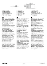
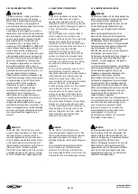
TEMPERATURE / RESISTANCE VARIATION / WIEDERSTANDSVERHALTEN
Temp.
PTO
PTC
PT 100 PT 1000 KTY84-130
0
200
400
600
800
1000
1200
1400
1600
-20
0
20
40
60
80
100 120 140 160 180
temperature [°C]
re
si
st
an
ce
[o
hm]
PTC
KTY
PT100
° C
Ω
Ω
Ω
Ω
Ω
-20
< 1
20…750
92,16
922
419
0
< 1
20…750
100
1000
493
20
< 1
20…750
107,79
1078
576
40
< 1
20…750
115,54
1155
668
60
< 1
20…750
123,24
1232
769
80
< 1
20…750
130,89
1309
880
100
< 1
20…750
138,5
1385
1000
120
< 1
20…750
146,06
1461
1129
140
< 1
20…750
153,58
1536
1268
150
> 1300
157,31
1573
1340
160
> 4000
161,04
1610
1415
180
> 4000
168,46
1685
1572

