47 - 97
Instruction Manual
AC 02/2019-rev.1.1
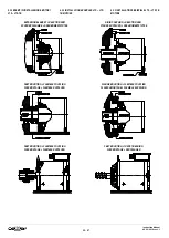
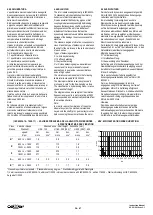
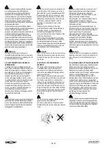
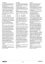
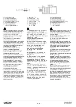
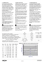
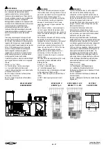
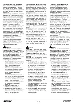
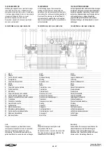
5.6 SCATOLA MORSETTI E MORSETTIERA
La scatola morsetti è posizionata di serie in alto o
sul lato della carcassa del motore.
La morsettiera del motore è collocata all'interno
della scatola morsetti mentre le morsettiere ed i
connettori per il collegamento di eventuali
accessori (Encoder, Freni etc.) sono poste sulla
carcassa del motore o sulla calotta di ventilazione.
5.6 TERMINAL BOX AND TERMINAL BOARD
The terminal box is normally positioned at the top
or on the side of the motor housing.
The terminal board is mounted inside of the
motor terminal box while the terminal boards and
the connectors for any accessories (Encoder,
Brakes etc.) are positioned on the motor housing
or on the fan guard.
5.6 KLEMMENKASTEN UND KLEMMENLEISTE
Der Klemmenkasten wird serienmäßig oben oder auf
der Seite des Motorgehäuses angebaut.
Die Klemmenleiste des Motors befindet sich im Inneren
des Klemmenkastens, während die Klemmenleisten für
den Anschluß von eventuellem Zubehör (Encoder,
Bremsen usw.) auf dem Motorgehäuse oder auf der
Lüftungsgehäuse angebracht sind.
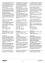
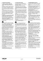
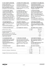
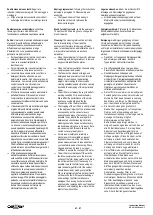
5.7 TOLLERANZA DELLA TENSIONE
I motori descritti in questo catalogo sono
progettati per essere alimentati con tensione
corrispondente al valore nominale di
avvolgimento. In presenza di variazioni
comprese tra il +/- 5% del valore nominale si
ottengono mutazioni delle caratteristiche del
motore che è comunque in grado di funzionare
senza significative variazioni di prestazioni.
In presenza di variazioni comprese tra il +/- 10%
del valore nominale è necessario richiedere un
avvolgimento speciale e declassare il motore.
5.7 TOLERANCE FOR SUPPLY
The motors described in this catalogue are
designed to be powered with a voltage
corresponding to the nominal value of the
winding. In the case of a fluctuation of up to +/-
5% on the nominal value there could be changes
in the characteristics of the motor, which will
however operate without any significant variation
in performance.
In the case of a fluctuation of over +/- 10% on the
nominal value, a special winding is required and
downrating of the motor becomes necessary.
5.7 SPANNUNGSTOLERANZEN
Die in diesem Katalog angeführten Motoren
wurden für eine Spannungsversorgung
entwickelt, die dem Nennwert der Wicklung
entspricht. Im Fall von Schwankungen im
B/- 5 % des Nennwertes ergeben sich
Änderungen der Motormerkmale. Der Motor läuft
jedoch ohne wesentliche Leistungs-
veränderungen.
Im Fall von Schwankungen im Bereich von +/-
10 % des Nennwertes ist eine Sonderwicklung
und eine Abklassierung des Motors erforderlich.
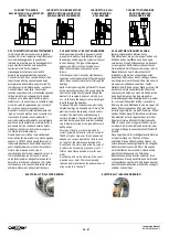
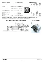
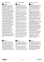
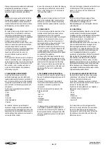
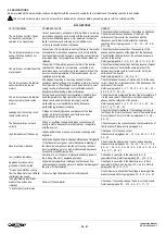
5.8 TOLLERANZE ELETTRICHE
Le tolleranze da applicare ai dati indicati nelle
tabelle tecniche sono definiti dalle norme IEC
60034-1.
Nella tabella sottostante sono indicate le
tolleranze riferibili ai motori alimentati da inverter.
5.8 ELECTRICAL TOLERANCES
The tolerances to be applied to the data shown in
the technical tables are defined by IEC 60034-1
standards. In the table below, the tolerances
referred to motors with inverter power supply are
shown.
5.8 ELEKTRISCHE TOLERANZEN
Die auf die Tabellenangaben anzuwendenden
Toleranzen sind in Norm IEC 60034-1 festgelegt.
In der nachstehenden Tabelle sind die Toleranzen
angegeben, die sich auf invertergesteuerte Motoren
beziehen.
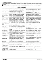
TOLLERANZE ELETTROMECCANICHE
ELECTROMECHANICAL TOLERANCES
ELEKTROMECHANISCHE TOLERANZEN
Rendimento,
Efficiency
, Leistung
P
n
50 kW
-15% of (1 -
)
P
n
> 50 kW
-10% of (1 -
)
Cos
,
Power Factor
, Leistungsfaktor
-1/6 (1 - cos
)
Scorrimento,
Slip
, Schlupf
20 %
Coppia massima,
Max. torque
, Max. Drehmoment
- 10 %
Momento d’inerzia rotorico,
Rotor inertia
, Läuferträgheit
10 %
Rumorosità,
Noise level
, Störpegel
+ 3 dB (A)
Vibrazioni,
Vibration
, Vibrationen
+ 10 %
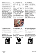
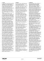
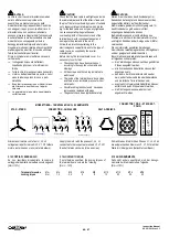
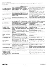
5.8.1 TOLLERANZE MECCANICHE
Le tolleranze meccaniche ed i gradi di precisione
di eccentricità rotazione albero, concentricità e
planarità della flangia di accoppiamento sono
definiti dalle norme IEC 72-1.
Nella tabella sottostante sono indicate le
tolleranze per altezza d’asse, diametro albero e
centraggio flangia.
5.8.1 MECHANICAL TOLERANCES
The mechanical tolerances and the precision
degree referring to shaft rotation eccentricity,
concentricity and flatness of the coupling flange
are defined by the IEC 72-1 standards.
In the table below, the tolerances for shaft
height, shaft diameter and flange spigot are
shown.
5.8.1 MECHANISCHE TOLERANZEN
Mechanische Toleranzen, Rundlaufgenauigkeit der
Welle, Konzentrizität und Planheit des
Kupplungsflansches sind in Norm IEC 72-1
festgelegt.
In der nachstehenden Tabelle sind die Toleranzen
für Achshöhe, Wellendurchmesser und
Flanschzentrierung angegeben.
TOLLERANZE MECCANICHE
MECHANICAL TOLERANCES
MECHANISCHE TOLERANZEN
Altezza d’asse,
Shaft height
, Achshöhe
H
250
0.5 mm
H > 250
1 mm
Diametro albero,
Shaft diameter
, Wellendurchmesser
11
28 mm
j6
38
48 mm
k6
55
110 mm
m6
Centraggio della flangia,
Flange spigot
, Flanschzentrierung
N
450 mm
j6
N
550 mm
js6

