94 - 97
Instruction Manual
AC 02/2019-rev.1.1
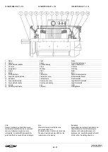
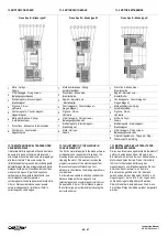
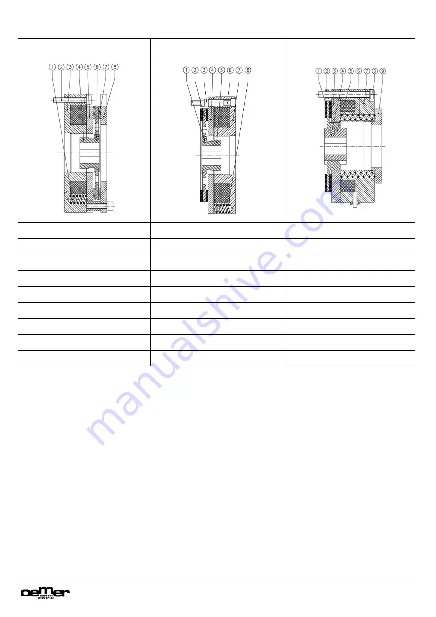
13.0 MOTORI CON FRENO
13.0 MOTORS WITH BRAKE
13.0 MOTORE MIT BREMSE
Freno tipo R
–
Brake type R
Freno tipo Rr
–
Brake type Rr
Freno tipo K
–
Brake type K
1
Molle -
Springs
–
Federn
1
Molla antivibrazione -
Spring -
Antivibrationsfeder
1
Disco freno -
Brake disk
–
Bremsscheibe
2
Viti di fissaggio -
Fixing screws -
Befestigungsschrauben
2
Disco freno -
Brake disk
–
Bremsscheibe
2
Registri -
Adjuster nuts
–
Einstellmutter
3
Elettromagnete -
Electromagnet
–
Elektromagnet
3
Registri -
Adjuster nuts
–
Einstellmutter
3
Contromagnete -
Counter-magnet
–
Gegen- Magnet
4
Pignone -
Pinion
–
Hohlwelle
4
Contromagnete -
Counter-magnet
–
Gegen- Magnet
4
Molla antivibrazione -
Spring -
Antivibrationsfeder
5
Contromagnete -
Counter-magnet
–
Gegen-Magnet
5
Pignone -
Pinion
–
Hohlwelle
5
Pignone -
Pinion
–
Hohlwelle
6
Molla antivibrazione -
Spring
–
Antivibrationsfeder
6
Viti di fissaggio
–
Fixing screws
–
Befestigungsschrauben
6
Molle -
Springs
–
Federn
7 Disco freno -
Brake disk -
Bremsscheibe
7
Elettromagnete -
Electromagnet
–
Elektromagnet
7
Elettromagnete -
Electromagnet
–
Elektromagnet
8
Controdisco -
Counter-disk
–
Gegenscheibe
8
Molle -
Springs
–
Federn
8
Viti di fissaggio -
Fixing screws
–
Befestigungsschrauben
9
Ghiera di regolazione -
Torque adj. Ring
–
Drehmoment Einstellring
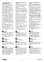
13.1 REGISTRAZIONE DEL TRAFERRO PER
USURA MATERIALE
Il materiale d’attrito a
pplicato al freno è destinato
ad usurarsi in base al numero delle inserzioni,
alla coppia di frenatura ed al tempo impiegato per
arrestare il motore. Tale usura comporta
l’allontanamento progressivo del contromagnete
dall’elettromagnete sino al raggiungime
nto della
distanza limite per cui il funzionamento del freno
viene compromesso. È’ pertanto opportuno
verificare periodicamente la distanza tra i due
nuclei magnetici (elettromagnete e
contromagnete) che deve essere contenuta entro
0.5 mm. Nel caso la distanza superi questo
valore è indispensabile ripristinare il traferro
corretto agendo come segue:
13.1 ADJUSTMENT OF THE AIRCORE IN
CASE OF WEAR-OUT
The friction material applied to the brake will wear
out depending on the number of insertions, the
breaking torque and the time necessary for
stopping the motor. This wear-out involves the
progressive removal of the electromagnet from
the counter-magnet until reaching a limit
distance; in this situation the braking operation is
compromised.
It is therefore advisable to check periodically the
distance between the two magnetic core
(electromagnet and counter-magnet) which must
be kept within 0.5 mm. If this distance is greater
the correct airgap must be reset by following the
instructions below:
13.1 EINSTELLUNG DES LUFTSPALTS FÜR
MATERIALVERSCHLEISS
Der an den Bremsen angebrachte Reibwerkstoff
nutzt sich entsprechend dem Einsatz, dem
Bremsdrehmoment und der zum Stillsetzen des
Motors benötigten Zeit ab. Dieser Verschleiß
führt zur fortlaufenden Entfernung des
Gegenmagnets vom Elektromagneten bis zum
Erreichen des Grenzwerts, an dem die
Bremsfunktion gefährdet ist. Der Abstand
zwischen den beiden Magneten (Elektro- und
Gegenmagnet), der unter 0,5 mm liegen muss,
sollte daher regelmäßig überprüft werden.
Überschreitet der Abstand diesen Wert, muss
der Luftspalt folgendermaßen wieder hergestellt
werden:

