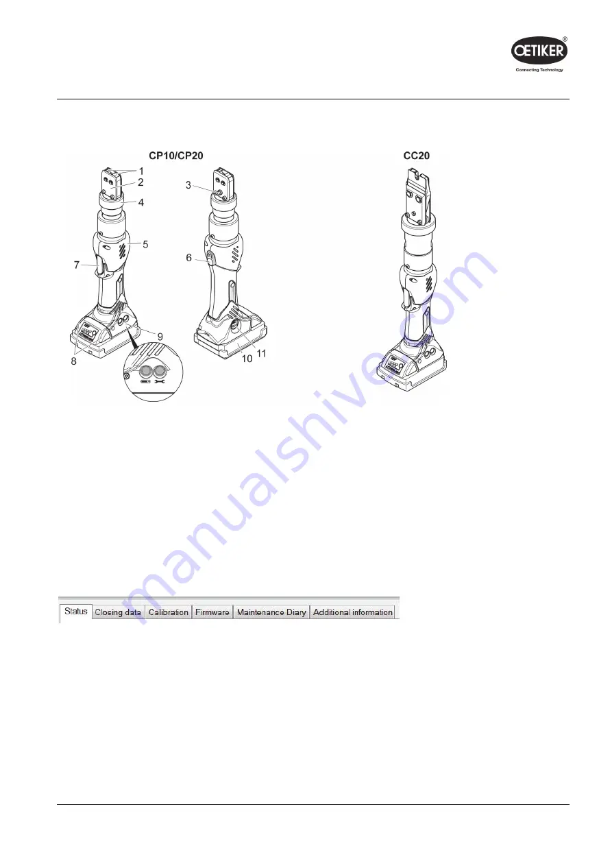
Clamp pincer CP 10 / CP 20 / CC 20
3
Overview
3.2
Clamp pincer CP 10 / CP 20 / CC 20
Fig. 2:
Clamp pincer CP 10 / CP 20 / CC 20
1 Pincer jaws
2 Pincer plate
3 Grease
nipple
4 Union nut
5 Pincer body
6 Reset
button
7 START button
8 Battery
release
9 Status
LEDs
10 Battery pack
11 USB port
3.3
Overview of PC software
The program interface is divided into 6 tabs.
•
Status: Display of the closing force curve and display of process data of the most recent closure or any
selected closure.
•
Closing data: Input and management of closing data set
•
Calibration: Activation of pincer calibration
•
Firmware: Upload of new operating software for the clamp pincer
•
Service log: Entry of desired or executed service measures
•
Additional information: Operation manual and contact information
Issue 11.15
08902961
3-12


