Officine Gullo
8
1. Commutator
2.
Commutator
3.
Electrical connection
4.
Switching terminal
5.
Resistance
6.
White pilot light
7.
Green pilot light
8.
Thermostat
9.
Safety Thermostat
INSTALLATION MANUAL
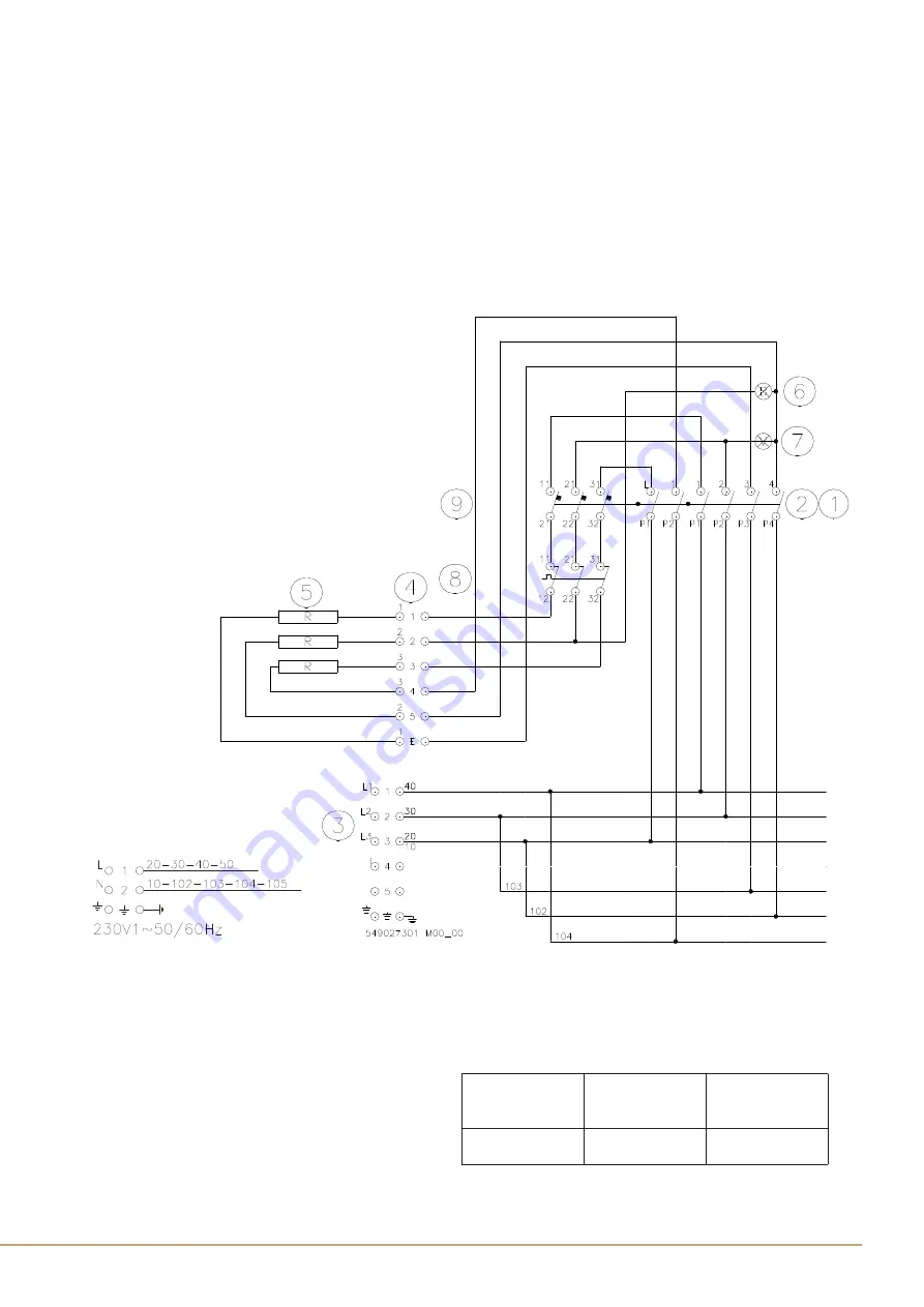
ELECTRICAL SCHEME
The installation of this appliance must conform with all applicable local codes.
In the absence of local codes, the installation must conform to the latest level of the National Electric Code, ANSI/NFPA
70.
If the electrical supply is not turned on or is interrupted the appliance will not operate. The applicable wiring diagram
for this appliance is below. The circuit where you wire your appliance to must be grounded and polarized. We
recommend the circuit for your appliance be a non-GCFI dedicated line.
FIG. A
SCHEMA ELETTRICO , SCHALTPLAN, SCHEMA ELECTRIQUE , WIRING DIAGRAM,
ESQUEMA ELECTRICO
549027301 M00_00
1-2
Commutatore Umschalter
Commutateur
Commutator Commutador
3
Morsettiera arrivo linea
Klemmleiste linie
Plaque à borne arr. Ligne
Electrical connection
Conexión eléctrica
4
Morsettiera di
commutazione
Terminal Einschalten
Plaque à borne
commutation
Switching Terminal
Terminal de
conmutación
5
Resistenza Heizelement
Résistence
Resistance
Resistencia
6
Spia bianca
Kontrolleuchte weiß
Lampe témoin blanche
White pilot light
Piloto blanco
7
Spia verde
Kontrolleuchte grün
Lampe témoin verte
Green pilot light
Piloto verde
8
Termostato
Thermostat Thermostat Thermostat
Termostato
9
Termostato sicurezza
Sicherheits-thermostat
Thermostat de sécurité
Safety Thermostat
Termostato seguridad
Model
Junction-box
Nr.1
Junction-box
Nr.2
F..S8EMU
Fig. A
Fig. A
Fig. A
9
Officine Gullo
INSTALLATION INSTRUCTIONS
This appliance is manufactured by OFFICINE GULLO S.r.l
Headquarters and factory
50012 Antella - Bagno a Ripoli (FI) Italy
via della Torricella, 29, - Tel. +39 055 6560324
In the US call
800 620 7490
Home page http:// www.officinegullo.com
E-Mail: info@officinegullo.com
Keep the appliance area free and clear from combustibles.
Do not obstruct the flow of combustion and ventilation air.
This manual shall be retained for future reference.
The manufacturer declines any responsibility for direct or indirect damage caused by improper or incorrect
installation, alterations, maintenance or use of the appliance, as in all the other cases considered in the items of our
sales conditions.
BEFORE YOU BEGIN
The manufacturer declines all responsibility in the event of failure to observe the instructions given here for installation,
maintenance and suitable operation of the product. The manufacturer further declines all responsibility for injury due
to negligence and the warranty of the unit automatically expires due to improper maintenance and/or installation.
BEFORE YOU BEGIN:
It is advisable to test run the oven before installation.
BEFORE STARTING
please read this entire document and ensure you are fully conversant with the require-ments and
limitations.
TECHNICAL ELECTRICAL DATA TABLE
DIMENSIONS
cm
POWER SUPPLY
Power max
kW
Absorbition
max A
Power supply cable
F...S8EMU
80 x 70 x 29h
230V 50/60 Hz
11,1
24,13 +
24,13
3x2,5 + 3x2,5 mm²
ELECTRICAL INSTALLATION
WARNING
: All electrical work must be performed by a qualified electrician.
Please ensure that the appropriate electrical codes or prevailing local building codes and ordinances are adhered
to.
Ensure that the electricity supply is disconnected at source. Do not use an extension cord or adapter plug with this
appliance.
This appliance must be grounded. Connect to a properly grounded branch circuit, protected by an appropriate
circuit breaker.


