background image

14

Officine Gullo 

EQUIPOTENTIAL

The appliance must be connected to an equipotential system.

The connection screw is positioned at the back of the appliance and is identified by the 

symbol 

.

Attention!

 The manufacturer will neither be held responsible for, nor will give any 

compensation during the guarantee period for any damage caused, and which is due to 

inadequate installations not compliant with the instructions.

CHECKING HEAT OUTPUT

The appliances must be checked in such a way as to verify that the heat output is correct:

• 

The heat output (thermal power) is indicated on the data plate of the appliance;

• 

Firstly, check that the appliance can be used with the type of gas supplied; then 

check that the indication on the plate corresponds to the gas to be used. For con-

verting to another type of gas, check that the type of gas complies with what is 

stated in this instruction manual.

The pressure is read with a gauge (minimum resolution of 0.1 mbar) inserted in the relative 

pressure outlet. (figure 1 item C).

Remove the hermetically closed screw and insert the gauge pipe.

After reading, put back the screw tightening it hermetically and check for pressure leaks.

Connection for liquid gas G30/G31

The connection pressure for liquid gas is 30 mbar with butane and 37 mbar with propane.

Check the plate, read the pressure and verify that the description of the nozzle installed 

corresponds to the one supplied by the manufacturer.

Connection with natural gas H G20

The connection pressure for natural gas is 20 mbar.

Check the plate, read the pressure and verify that the description of the nozzle installed 

corresponds to the one supplied by the manufacturer.

CHECKING PRIMARY AIR TO THE MAIN BURNERS AND PILOT NOZZLES

All the burners are fitted with an air regulator by means of which the primary air can be varied 

thanks to an adjustable bush that can be locked with a screw. In the “Burner Technical Data” 

table you will find the approximate values for the “h” parameter (primary air). The flow of 

primary air must be regulated so there is no detachment of the flame when the burner is cold 

or a return of the flame when the burner is hot.

The pilot air is regulated when the appliance is tested and inspected for the gas it is set for.

If you are going to change to a different type of gas, regulate the air by means of the adju-

sting bush until the flame stops sputtering and becomes an intense blue colour.

Summary of Contents for GGS8P

Page 1: ...INSTRUCTIONS for installation and use RANGE WITH OVEN FOR RESIDENTIAL AND PROFESSIONAL USE GGS8P GGS12P GGPS8P GGPS12P GES8P GES12P GEPS8P GEPS12P...

Page 2: ...appliance s maximum power consumption The use of adapters multiple power boards and extension cords is not recommended 8 When not in use switch off the general power supply to the appliance and close...

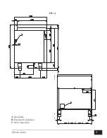
Page 3: ...3 Officine Gullo A Data plate B Electrical Connection C Gas Connection FIG A...

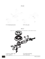
Page 4: ...ackofen Bypass By pass four Oven by pass By pass horno FIG F PC GP CF GP FUOCHI FLAMME FEUX COOKING RINGS FUEGOS 562047300M00P00 1 2 3 4 1 Iniettore fuochi Einspritzventil flamme Injecteur feux Inject...

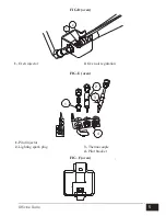
Page 5: ...ilota Einspritzv Z ndBrenner Injecteur veilleuse Pilot Injector Inyector piloto 2 Candela accensione Z ndkerze Bougie d allumage Lighting spark plug Candela encendido 3 Termocoppia Thermoelement Therm...

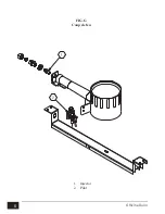
Page 6: ...6 Officine Gullo FIG G Coup de feu 1 Injector 2 Pilot...

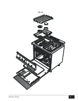
Page 7: ...7 Officine Gullo 5 FIG K FIG H...

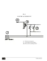
Page 8: ...8 Officine Gullo ELECTRICAL SCHEME TOP 1 Electrical connection 2 Push button starting burner 3 4 Power station starting burner FIG I...

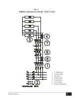
Page 9: ...9 Officine Gullo WIRING DIAGRAM STATIC OVEN GN2 1 1 Commutator 2 Junction box 3 Element 4 White light 5 Green light 6 Thermostat 7 Safety thermostat FIG L...

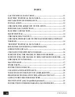
Page 10: ...HNICAL DATA TABLE 15 RULES FOR CONVERTING AND INSTALLING OTHER TYPES OF GAS 16 CHANGING THE OPEN RING NOZZLES 16 SUBSTITUTING THE NOZZLE IN THE OVEN BURNER 16 SUBSTITUTING THE NOZZLE IN THE COUP DE FE...

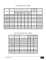
Page 11: ...1 1 1 1 27 3 R3 4GM GEPS8P 80x70x90h 1 1 1 20 R1 2GM 3 4GM 1007 GGPS12P 120x70x90h 1 2 1 1 1 36 3 R3 4GM GEPS12P 120x70x90h 1 2 1 1 29 R3 4GM MODEL Dimensions cm Power Supply Tot power KW Max absorb...

Page 12: ...ch are formed during combustion The air necessary for combu stion is 2m3 h per kW of power installed Attention In accordance with international rules when connecting the appliance an au tomatic device...

Page 13: ...pipes or otherwise with flexible steel pipes in compliance with the national norms if any exist Each appliance must be provided with a cut off cock for rapid interruption of the gas supply Once the ap...

Page 14: ...rew tightening it hermetically and check for pressure leaks Connection for liquid gas G30 G31 The connection pressure for liquid gas is 30 mbar with butane and 37 mbar with propane Check the plate rea...

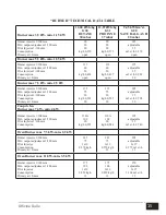
Page 15: ...injector 1 100 mm Min output adjustment 1 100 mm Pilot Injector 1 100 mm Consumption Primary air h mm 135 75 20 kg h 0 591 20 135 75 20 kg h 0 582 20 205 adjustable 35 m3 st h 0 794 20 Coup de feu Bur...

Page 16: ...able spanner see burners technical data table Regulate the air regulation bush to the corresponding value in the technical data table by unscrewing the fixing screw with relative jam nut regulate mini...

Page 17: ...end drawing up a contract for after sales service Maintenance must be done only by specialized personnel observing the norms in force and our indications SPARE PARTS Coup de feu It is possible to subs...

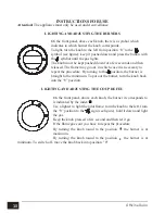
Page 18: ...ary to repeat the procedure By turning to the position the burner is brought to the minimum To put out the burner turn the knob back into the 0 position LIGHTING AND ADJUSTING THE COUP DE FEU On the f...

Page 19: ...turn off the oven turn the knob to the right into position 0 Attention When the oven is on the door must not remain open because it could heat and damage the knobs LIGHTING AND REGULATING THE ELECTRI...

Page 20: ...ils in order to avoid spoiling the beauty of the brass with an artificial patina The antique finish of the surface is the result of natural oxidation that has simply been accelerated All the natural a...

Page 21: ...neutral detergent and where necessary a soft possibly micro fiber cloth Do not use abrasive pads or any other chemical products CLEANING BRUSHED STEEL SURFACES All the brushed steel surfaces should b...

Page 22: ...ctly to the outside is acceptable Forced Discharge Fig 2 but its capacity must not be inferior to what is established in item 4 3 of the UNI CIG norm 8723 In the event of forced discharge The gas supp...

Page 23: ...23 Officine Gullo...

Page 24: ...WWW OFFICINEGULLO COM V 1 0 10 17 OFFICINE GULLO S R L via della Torricella 29 50012 Antella Bagno a Ripoli FI Tel 39 055 6560324 621807 Fax 39 055 620670 info officinegullo com en INTERNATIONAL...

Reviews: