6
14
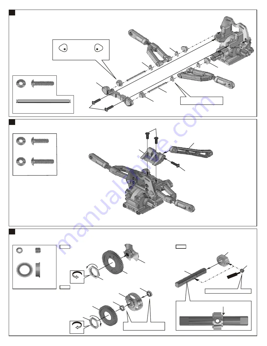
ASSEMBLY OF THE REAR BRACE
15
ASSEMBLY OF THE REAR UPPER ARMS
40716(2mm)
40716(1mm)
40546
*Insert the caster angle adjuster
onto arm shaft.
40719
40719
40719
4x16mm
4x12mm
40539
.....x2
94011
4x16mm
Hex Screw
.....x2
40546
3x42.7mm
Arm Shaft
*Set the left and right hand side upper arm
adjuster in the same direction.
Left
Right
.....x1
94011
4x16mm
Hex Screw
.....x2
94010
4x12mm
Hex Screw
ASSEMBLY OF THE TWO SPEED GEARS
16
40539
4x16mm
Step 1
35225
1st Spur Gear
Holder (One Way)
35248
1st Spur Gear
(48T)
35228
35230
40112
35235
5x5mm
.....x2
.....x1
94036
5x5mm
Set Screw
35230
8x12mm
Flange Bearing
35219
Clockwise
35244
2nd Spur Gear
(44T)
35234
2nd Spur Gear
Holder
*Put the clutch shoe carrier to the edge of the groove on
the shaft.
Anti Clockwise
Step 2
Step 3
35230
Rotate
Direction
Sc
rew
Ce
me
nt
Rotate
Direction
*Push the flange ball bearing
into clutch bell.
*Place the set screw in the "D" cut.
Summary of Contents for DM-1 Spec
Page 1: ...OFNA 7 VANDERBILT IRVINE CA 92618 PH 949 586 2910 FAX 949 586 8812...
Page 2: ......
Page 32: ......


