background image

PARTS USED

Assembly of the right and left-side are
the same.  

L

10 x 15mm 
        Ball Bearing        x2 

37450

5 x 11mm
Ball Bearing             x2  

37430

37751

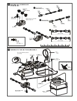
ASSEMBLY OF THE FRONT KNUCKLE ARMS

Front Knuckle Arm
( Left )

8mm  
Steering Ball

8mm  
Steering Ball              x4

8mm
Steering 
Ball Washer

10mm 
 Hex Screw

10mm 
 Hex Screw                x4

5mm 
Hex Wrench 

Front Knuckle Arm
( Right)

39150

39150

39140

39140

39141

39090

39090

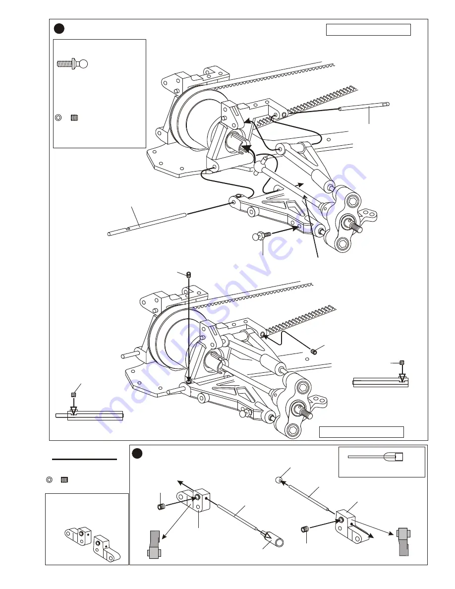
ASSEMBLY OF THE CVA UNIVERSAL SHAFT

Assembly of the right and left-side are
the same.  

0              10             20             30             40             50

mm

PARTS USED

3 x8mm 
      Set Screw       x2

9

9

10

10

11

11

ASSEMBLYOF THE  FRONT SUSPENSION ARMS

* "L" make for left-side.

37430

37450

10 x 15mm
Ball Bearing

37450

10 x 15mm
Ball Bearing

5 x 11mm
Ball Bearing

37430

5 x 11mm
Ball Bearing

L L

CVA Joint 
Constant Velocity Axle

39190

CVA Joint 
Constant Velocity Axle

39190

* Notice the left and right-side arm
   is difference angle.  

( Right )

( Left )

 * Push  ball bearings into
    knuckle arm as shown.

Push

Push

39050
Front Upper Arm

2 .5mm Hex Wrench

3 X 8mm
Set Screw

39060
 Front Lower Arm

Leave approx 
       3mm 

* A 3 x 8mm set screw is used 
   to adjust  the ride height.

L L

Leave 2mm

Leave 2mm

* Make steering ball 
  move smooth. 

Front Knuckle Arm
Assembly

• Lower arm down 
stop.

Assembly of the right and left-side are
the same.  

ASSEMBLY OF THE FRONT SUSPENSION ARM TO ARM BLOCK 

37360

37751

4mm Ball Socket       x2

3 x 3mm 
      Set Screw       x4

12

12

39070
Upper Arm Shaft

38240
Lower Arm Shaft

3 x 3mm 
      Set Screw       x2

PARTS USED

Stabilizer Mount

Stabilizer Mount

3 x 3mm
Set Screw

3 x 3mm
Set Screw

Stabilizer Ball

Stabilizer Ball
Block

38090
 1.6 x 35mm
 Stabilizer

38090
 1.6 x 35mm
 Stabilizer

ASSEMBLY OF THE FRONT STABILIZER

13

13

39060

39060

39060

39060

* Insert F-09B as shown.

37360
4mm 
Ball & Socket

L L

* Insert the drive shaft before 
  assembly.

3 x 3mm 
      Set Screw       

* Set 3 x 3mm set screw
   in " D" cut.  

Assembly of the right and left-side are
the same.  

3 X 3mm
Set Screw

3 X 3mm
Set Screw

3 x 3mm 
Set Screw       

* Set 3 x 3mm set screw
   in " D" cut.  

L L

OPTION PART: 39467 
                          Alum. Stabilizer
                          Mount

Summary of Contents for nitro OB 4

Page 1: ...building experience in order to assemble the model correctly and to produce it s performance to full extent Assemble this kit only in places out of children s reach Take enough safety precautions prio...

Page 2: ...Phillips Type Screw Drivers L Phillips Type Screw Drivers S Needle Nose Pliers Cutter Curved Scissors Knife Instant Cemment Cross Wrench 17109 Masking Tape Paints Brush Precision Caliper SUITABLE SER...

Page 3: ...ou will not be able to off Fuel contains Methanol and Nitro Methane and is drive it without hitting something flammable and poisonous Do not operate the car indoors Engine exhaust is not healthy Store...

Page 4: ...ing nut 37962 Adjust Nut Blue 37963 Adjust Nut Purple Oil 37650 4mm Ball End Make pair for rear 1 1 2 3 SHOCK ASSEMBLY Long 37650 4mm Ball End Make pair for front Short Shock Oil Silicone 37080 Pressu...

Page 5: ...iveness of the gear differential hold the gear tightly with one hand and turn one cap joint Does the other cap joint move in the opposite direction and smoothly If gear differential does not smoothly...

Page 6: ...11 12 13 Looser Tighter 1 2 3 4 5 6 8 9 1 0 1 1 1 2 1 3 CHECKING YOUR DIFFERENTIAL ASSEMBLY To test the effectiveness of the gear differential hold the gear tightly with one hand and turn one cap joi...

Page 7: ...t Long OPTION PARTS 39460 Front Ball Differential ASSEMBLY OF THE FRONT ARM BLOCK OPTION PARTS 34961 Rear Ball Differential 39050 39458 Complete PARTS USED OPTION PARTS 39471 Alum Suspension arm Block...

Page 8: ...ARTS USED 3 x8mm Set Screw x2 9 9 10 10 11 11 ASSEMBLYOF THE FRONT SUSPENSIONARMS L make for left side 37430 37450 10 x 15mm Ball Bearing 37450 10 x 15mm Ball Bearing 5 x 11mm Ball Bearing 37430 5 x 1...

Page 9: ...x 3mm Set Screw Stabilizer Ball Stabilizer Ball Block 38090 1 6 x 35mm Stabilizer 38090 1 6 x 35mm Stabilizer ASSEMBLY OF THE FRONT STABILIZER 13 13 39060 39060 39060 39060 Insert F 09B as shown 37360...

Page 10: ...m 2mm o change the caster angle use adjuster t 39090 Caster Angle Adjuster 6 L L 39417 Front Lower Arm Stiffener Keep stabilizer ball in the center Turn stabilizer balance adjuster to adjust the stabi...

Page 11: ...r Wheel Hub 39100 Rear Wheel Hub ASSEMBLY OF THE REAR WHEEL HUB BAG 4 Step 17 23 17 17 23 keep 8mm steering ball smooth 39141 8mm Steering Ball Washer 39141 8mm Steering Ball Washer 39130 Rear Wheel A...

Page 12: ...ERENTIAL INTO REAR BLOCK 10 x 15mm Ball Bearing x2 37450 PARTS USED PARTS USED 37450 10 x 15mm Ball Bearing 37450 10 x 15mm Ball Bearing 39415 Rear Diff Adapter 39415 Rear Diff Adapter 39110 Rear Bloc...

Page 13: ...are the same ASSEMBLY REAR BLOCK COVER AND REAR LOWER ARMS Insert rear belt before assembly 39319 150 Belt Rear Set the 3x3mm set screw in D cut 3 x 3mm Set Screw 38240 rear lower arm shaft 3 x 15mm...

Page 14: ...shown 3 x 15mm Screw x2 39417 Lower Arm Stiffener 3 x 15mm Screw 3 x 15mm Screw 3x10mm Tapping Screw 3x10mm Tapping Screw 3 x 10mm Tapping Screw x2 20 21 ASSEMBLY OF THE REAR LOWER ARM STIFFENER ASSEM...

Page 15: ...3 x 15mm Screw 3mm Nylon Nut Rear Upper Rod 39408 Rear Drive Shaft Insert rear drive shaft before assembly OPTION PARTS 39463 Alum Main Shaft Bulk Head STOCK PARTS 37929 Graphite Brake Disk OPTION PA...

Page 16: ...e LONGER Disc Mount found in bag 5 or plastic tree 39415 There may be a similar part that is shorter and not correct This is due to the 2 speed shaft and dual brake configuration 37400 Do Not Use OPTI...

Page 17: ...pping Screw 39413 Main Shaft Bearing Bulkhead 3 x 10mm Flat Head Tapping Screw x4 26 ASSEMBLY OF THE MAIN SHAFT ONTO CHASSIS Insert the rear belt onto pulley before assembly OPTION PARTS 37943 Alum 15...

Page 18: ...rrier One Way 35937 2nd Gear Carrier Ball Bearing Notice the direction of the clutch cam 3 x 3mm Set Screw 37400 2 x 8 8 Pin 4mm E Ring 4 mm E Ring x2 37390 37751 2 x 10 8mm Pin x1 u w E Insert the 2x...

Page 19: ...3 Mid Shaft Block 2 x 8 8mm Pin 4mm E Ring Pulley Mount 38050 4mm E Ring 39409 Mid Shaft Pulley Washer 3 x 10mm Flat Head Tapping Screw x4 3 x 10mm Flat Head Tapping Screw 3 x 10mm Flat Head Tapping S...

Page 20: ...le Belt Stiffener 39318 Belt Guide 39318 Roller Washer ASSEMBLY OF THE MIDDLE BELT 30 OPTION PARTS 37943 ALUM PULLEY MOUNT 38070 177 Belt 39318 Belt Tension Roller kit 4 mm E Ring x1 3 x 10mm Screw x1...

Page 21: ...RY HOLDER 39416 Battery Holder 37420 Sided Tape Use strong tape to secure the battery 6V 600mhA ncad or NEW 6V1000mhA Ni Mh 10211 29 95 Ni Mh Charger 10214 7 95 3 x 3mm Set Screw x2 The 6V battery is...

Page 22: ...tenna Wire Cable Tie Tighten the cable tie and cut off the excess 3 x 10mm Tapping Screw 10273Servo Mount 10273 Servo Mount 39423 Black Alum Radio Tray 39414 3mm Servo Washer 39414 3mm Servo Washer AS...

Page 23: ...ew 10273 Servo Mount 10273 Servo Mount OPTIONAL ASSEMBLY OF THE FLAT BATTERY PACK 39423 Radio Tray Black Alum 39414 3mm Servo Washer 39414 3mm Servo Washer If using a slide carburetor on your engine a...

Page 24: ...Ball Socket Servo Saver Servo Saver Adapter For KO Futaba JR Choose the correct servo saver adapter for you servo Steering Servo Rod Righthand Side Long A A Steering Servo Rod Lefthand Side Short B B...

Page 25: ...hoes 10010 10100 Shoes are trailing 12 15 Class Side Exhaust Engine 3 shoes flywheel Pilot Shaft 59020 59021 HN HN 3 x 5mm Screw Note Counter clockwise rotation of the flywheel HN HN 3mm Nylon Nut 3mm...

Page 26: ...10mm Tapping Screw 3x10mm Tapping Screw 3x10mm Tapping Screw 3x10mm Flat Head Tapping Screw 37360 4mm Ball Socket Snap onto 37360 ball Socket HN HN 38161 3 x30mm Screw 38161 Muffler Gasket 37935 Manif...

Page 27: ...Screw 3 x 10mm Screw Screw in 3 x 10mm screws from the bottom of the chassis Use note book paper to set gear backlash between spur gear and clutch bell gear If the space is not correct the spur gear...

Page 28: ...A A 43 43 BRAKING NEUTRAL ENGINE AT IDLE FULL THROTTLE Brake is on Full brake stopper pushing on brake lever and throttle still in idle with spring movement Brake is off Neutral position throttle is...

Page 29: ...TTLE FOR SLIDE CARBURETOR 45 45 Brake is on Slider ASSEMBLY OF THE THROTTLE LINKAGE For slide carburetor Step 2 ASSEMBLY OF THE THROTTLE LINKAGE PARTS USED 3 x 3mm Set Screw x2 2 6mm Nut x1 Alum Stopp...

Page 30: ...rburetor Fuel Tube 30491 Muffler Stay 32890 Muffler Cable Tie Cable Tie ASSEMBLY OF THE MUFFLER 10079 Pressure Nipple 38163 Silicon Tube 46 46 Strap INSTALLATION OF AIR FILTER 39473 Holder with foam d...

Page 31: ...t the larger hole 3 x 10mm Screw x4 PARTS USED 37955 6mm Alum Ball Socket x4 3 x10mm Screw 37955 6mm Alum Ball Socket 2mm Plastic Washer Take 2mm plastic washer from shock plastic parts Take 2mm plast...

Page 32: ...t Rear 3x10mm Tapping Screw 3x10mm Tapping Screw 50 50 51 51 ASSEMBLY OF THE TIRES AND WHEELS Apply instant cement 87613 Split Spoke white Wheel 24mm 87614 Split Spoke black Wheel 24mm 87615 Split Spo...

Page 33: ...8 Pin x4 37390 10376 M4 Nylon Nut X4 4mm Nylon Nut Driver Nut Alum FRONT ASSEMBLY L L 37390 2 x 10 8mm Pin Driver Nut Alum REAR ASSEMBLY 37390 2 x 10 8mm Pin 4mm Nylon Nut ASSEMBLY OF THE WHEELS INTO...

Page 34: ...SHIFT UP TIMING ADJUSTMENT 2 SPEED GEAR RATIO COMBINATIONS 2 SPEED OPTION PARTS IMPORTANT The sum of the spur gear and clutch gear for1st gear must be equal the sum of the spur gear and clutch gear fo...

Page 35: ...tter controls and trims are in neutral 2 Switch on transmitter 3 Switch on receiver Inspect operation using transmitter before running Revers sequence to shut down after running and make sure to disco...

Page 36: ...ERING BALL WASHER and CASTER ADJUSTER x2 39090 FRONT KNUCKLE ARM x1 Left Right 37660 15 PULLEY x1 Right Left Left Right 2 H 6 9 C B1 B3 B2 Short 37661 16T 17T Pulley Gear x1 39406 FRONT BUMPER x1 3765...

Page 37: ...r will make the front tires become toe out Response will be quicker and will under steer Adjust the length of the rear hub 8mm ball to change the toe angle Making the 8mm ball longer will make the rea...

Page 38: ...ap 8 Lap9 Lap10 Lap11 Fuel Single Speed T T T T 1 2 2 Speed HARDNESS OF DIFF Rear The 39450 2 speed transmissionallows the car tohave more punch outof the corners andhigher top speed We offer many dif...

Page 39: ...ear Rear Rear Rear Neutral Position Toe Out Toe Out Toe In A A B A mm B mm A mm B mm TOE IN and TOE OUT N N N N SHOCK ANGLE AB AB HARDNESS OF SPRING H H M M S S SHOCK OIL 10W 20W 30W 40W 50W 60W 10W 2...

Page 40: ...E F C F TEMP SETUP SHEET WET TIRE R T T T T T T T T 1 2 1 2 GEAR RATIO Front Center BEST LAP 1 2 3 4 5 6 7 8 Lap 1 Lap 2 Lap3 Lap 4 Lap 5 Lap 6 Lap 7 Lap 8 Lap9 Lap10 Lap11 Spur Gear Clutch Gear Hardn...

Page 41: ...ted let engine fast idle for two tanks of fuel Close master needle by turning clockwise until it stops Then open needle by turning counterclockwise 3 turns rich setting When running car adjust carb wi...

Page 42: ......

Page 43: ......

Reviews: