6
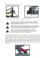
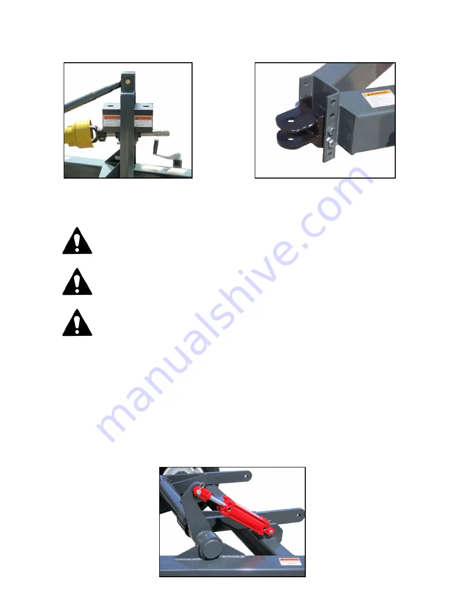
Attach the Top Link using Pin and Hairpin.
Attach the Tongue Clevis using two 5/8” x 6” Capscrews and Nylock Nuts.
WARNING:
Always wear protective eye goggles and use a magnifying
Glass or hold a piece of wood on suspected leaks. Pinhole hydraulic leaks
can penetrate skin. Do not touch.
CAUTION:
Make sure a restrictor is installed in one of the hydraulic lines.
Failure to use a restrictor will allow the machine to raise and lower rapidly
and could result in damage to the machine and injury to bystanders.
CAUTION: Operate the cylinder through the cycle a few times to
expel air from the system. Failure to fully charge the hydraulic system
could result in injury when the mower falls abruptly.
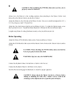
Mount the Hydraulic Cylinder on the Carrier and install two ½” NPT Male x 3/8” JIC Male
Elbows in the Hydraulic Cylinder.
Note:
Do not use Teflon tape, only use liquid type thread
sealant. Attach the 114” Hose with ½” NPT Male - 3/8” JIC Swivel ends to the front port of the
Hydraulic Cylinder. Attach the 122” Hose with ½” NPT Male – 3/8” JIC Swivel ends to the rear
port of the Hydraulic Cylinder. Install the Restrictor on one of the Hydraulic Hoses before
installing a Hydraulic Coupler. Route the Hydraulic Hoses through the loop on the side of Drive
Shaft Support Weldment and then to the tractor. Before attaching a Mower to the Mower Carrier
operate the Hydraulic Cylinder several times to purge the air out of the system to prevent any
sudden drop.
A
A
T
T
T
T
A
A
C
C
H
H
I
I
N
N
G
G
M
M
O
O
W
W
E
E
R
R
Summary of Contents for BCH610
Page 2: ......
Page 13: ...11 Notes ...
Page 14: ...12 ...
Page 16: ...14 Notes ...
Page 18: ......
Page 19: ......

