MANUAL NO. 33
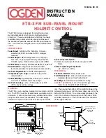
ETR-3 FM SUB-PANEL MOUNT
HI-LIMIT CONTROL
INSTRUCTION
MANUAL
The ETR-3 Series is designed for industrial and com-
mercial applications which require high temperature
protection. These controls feature a latching, manually
resettable relay output which de-energizes whenever
the sensed temperature exceeds the set point tempera-
ture. It can also be configured as an on-off temperature
control.
SPECIFICATIONS
Power Input:
120VAC ±15%, 50/60Hz, 3VA max.
standard (240VAC and other AC/DC voltages
optional).
Control Output:
SPDT Relay rated 3.8 (1.5) Amps
Res. and 1.5 (.8) Amps Pilot Duty 120 (240)VAC.
100,000 cycles. Optional DC output to drive SSR.
Control Mode:
Latching with Manual Reset or power off.
Reset Function:
Integral reset switch standard;
terminals available for optional remote reset switch.
Set Point Adjustment:
Local SP dial adjustment.
Compensation (TC only):
Automatic cold junction
compensation.
Control Stability:
Typically less than ±5µV/°F ambient
and 0.1% of SPAN/% rated line voltage.
Set Point Accuracy:
±3% of FS maximum at 78°F
(25°C) and rated line voltage.
Sensor Break Protection:
Contacts 4 and 5 open for thermocouple or RTD
break.
Ambient Operating Temperature:
32 - 140°F (0 - 60°C).
MECHANICAL
Enclosure Material:
Noryl, Black color.
Field Terminations:
Screw Terminals with wire
clamping plates and touch safe shield.
Mounting:
35mm DIN rail or surface mounting.
AGENCY APPROVALS:
UL 873 and CUL per CSA
C22.2 No.24 File #E179225; FM 3545.
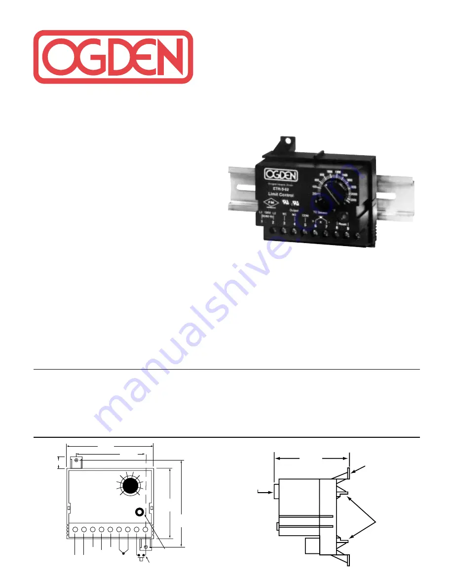
3-5/16"
(84mm)
2-9/16"
(65mm)
3/8"
(9.5mm)
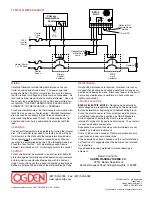
1
2
3
4
5
6
7
8
9
2-1/2"
(63.5mm)
3"
(76.2mm)
Power
Input
Relay
Output
TC or
RTD
Sensor
Optional N.O.
Remote Reset
Switch
Integral Reset
Button
RESET
Limit Controller
L1
L2
N.C.
N.O.
COM
+
–
150
200
350
300
°
F
+ –
AC
DC
2-1/2"
(63.5mm)
Panel mounting foot
with clearance holes
for #8 screw
(2 places)
35mm
DIN rail
mounting clips
Set point
adjust
DIMENSIONS:
MOUNTING
The ETR-3 can be surface mounted or mounted on a DIN
rail. The ETR-3 must be located inside a suitable control
enclosure. It can be mounted to any suitable flat surface
using two #8 screws (not supplied). To install simply
position the top set of rear clips over the top of the DIN
rail. Then swing the bottom of the controller toward the
rail applying pressure until the lower clips snap on to the
bottom of the DIN rail. To remove apply pressure to the
top of the controller’s base and move the bottom of the
controller toward you. Then lift the top pf the controller
off the upper DIN rail.


