5 9 Dual Set Point / PID
5 9 Dual Set Point / PID
The ETR-8300 will switch between the two PID sets based on the process
value, the set point or the event input. As the control ramps up to a higher
process value, the process characteristics can change. As this happens, the
original PID values are no longer valid. To achieve optimal control over the
entire range, a second PID set is used.
Example 1: Single Set Point / Dual PID
Example 1: Single Set Point / Dual PID
A heat treating furnace is used over the range of 400 °C to 1200 °C.
A heat treating furnace is used over the range of 400 °C to 1200 °C.
( 1 ) Set the following parameters in the Setup menu:
( 1 ) Set the following parameters in the Setup menu:
FUNC= FULL
A1FN= PV1H
A1MD= NORM
EIFN= PID2
PVMD= PV1
SPMD= MINR
FUNC= FULL
A1FN= PV1H
A1MD= NORM
EIFN= PID2
PVMD= PV1
SPMD= MINR
( 2 ) Adjust the following parameters in the User menu:
( 2 ) Adjust the following parameters in the User menu:
A1SP= 800 °C
A1HY= 1.0 °C
Pl1= 100 ( % )
RAMP: According to the process requirement
SP1: According to the process requirement
A1SP= 800 °C
A1HY= 1.0 °C
Pl1= 100 ( % )
RAMP: According to the process requirement
SP1: According to the process requirement
( 3 ) Lastly, tune PID set one with a SP1= 500 °C, then tune the second PID set with
a SP1=1100 °C, or set the proper values for PB1, Ti1, TD1, PB2, TI2 and TD2
according to previously existing records to eliminate the need for auto-tuning.
( 3 ) Lastly, tune PID set one with a SP1= 500 °C, then tune the second PID set with
a SP1=1100 °C, or set the proper values for PB1, Ti1, TD1, PB2, TI2 and TD2
according to previously existing records to eliminate the need for auto-tuning.
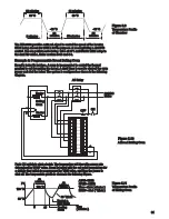
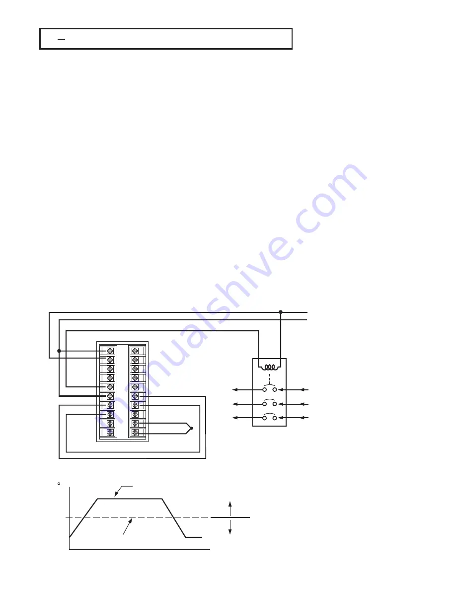
The circuit diagram and its temperature profile are shown as follows :
The circuit diagram and its temperature profile are shown as follows :
To
Furnace
Heater
To
Furnace
Heater
Heater
Power
Input
Heater
Power
Input
AC power
AC power
Alarm 1 controls
Event input
Alarm 1 controls
Event input
Figure 5.14
Figure 5.14
Dual PID Furnace
Dual PID Furnace
Process Value
Process Value
PID Crossover Value
PID Crossover Value
Use PID 1
Use PID 1
Use PID 2
Use PID 2
Time
C
800
Figure 5.15
Figure 5.15
Dual PID Crossover
Dual PID Crossover
94
1
2
3
4
5
6
7
8
9
10
11
12
13
14
15
16
17
18
19
20

