INSTRUCTION
MANUAL
MANUAL #27
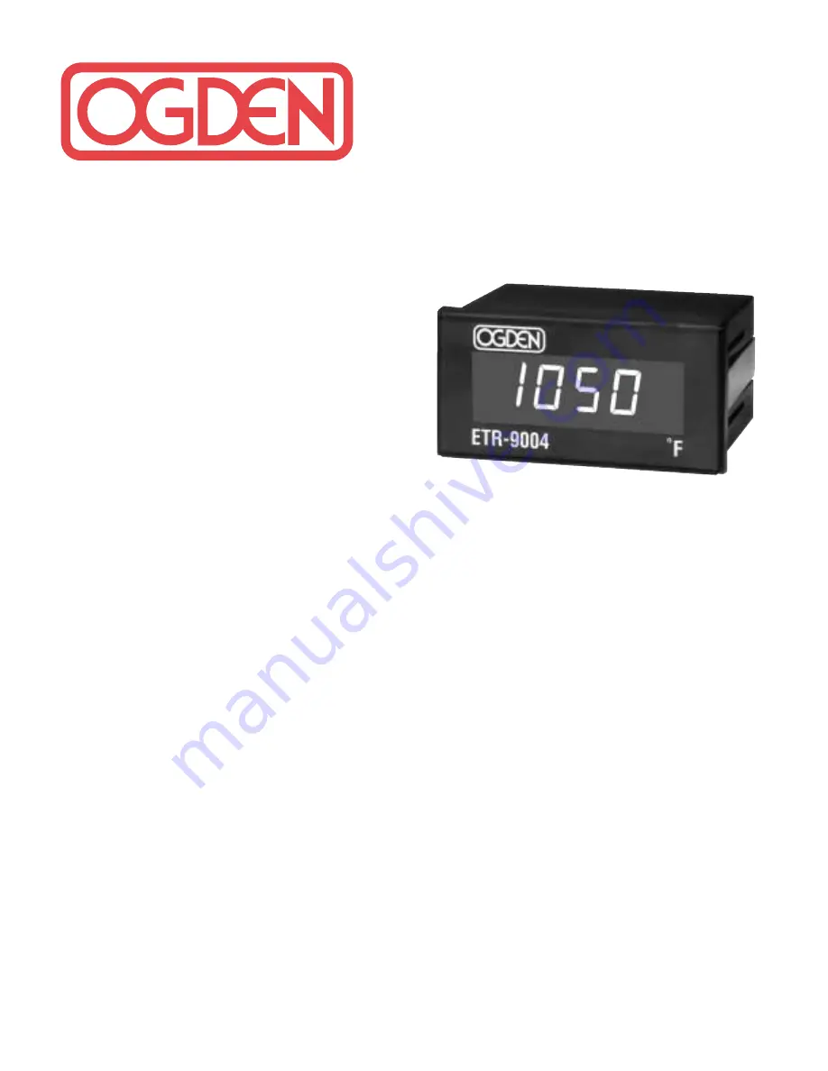
1/8 DIN Solid State Temperature
Indicator Model ETR-9004
All temperature indicators in this series are made to fit
into panel cut-outs which measure 1
13
⁄
16
” x 3
5
⁄
8
” (46mm x
92mm). A minimum of 3
1
⁄
2
” (89mm) in depth is required
for electrical clearances of rear terminal connections.
The following specifications are common to all models:
INPUT
Thermocouple (T/C)
Type K, J. Specified on
Control Label.
RTD
PT 100 ohm, 2 or 3-wire
(
= .00385) DIN
(
= .00392) JIS
Cold Junction
Compensation
Automatic
Input Break
Built-in, upscale on open
sensor.
Input Impedance
1M ohm.
Common Mode
Rejection (CMR)
CMRR 120dB, Min.
Normal Mode
Rejection (NMR)
NMRR 60dB, Min. (60Hz)
POWER
Rating
120/240VAC field
selectable, 50/60Hz.
12-24VDC models
available on special order.
Accuracy
0.2% of SPAN.
Consumption
Less than 3VA.
ENVIRONMENTAL & PHYSICAL
Operating Temperature 10° to 125°F (-12 to 52°C).
Humidity
5 to 90% RH (non-
condensing).
Insulation
20M ohm Min., (5000VDC).
Breakdown
2000VAC, 50/60Hz,
1 minute.
Vibration
10 - 55Hz, Amplitude
1.0mm.
Shock
660 ft./S
2
(20g.)
Weight
11 oz. (312 grams)
DIMENSIONS
H – 1
7
⁄
8
” (48mm)
W – 3
3
⁄
4
” (96mm)
D – 3
1
⁄
4
” (83mm)
Depth behind panel – 3”
(76mm)
DIN Case
Plastic, with screw
terminals on rear,
adjustable brackets for
panel mounting.
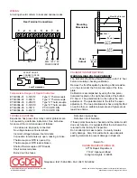
MOUNTING
When mounting the instrument, it is important the
instrument remains within the ambient temperature
range of 10 to 125°F. Mounting it in any position is
permissible. After inserting the instrument into the
panel, secure it with the mounting bracket provided with
each unit.
•
Both solderless terminals or “stripped” leads
can be used for power leads. Only “stripped” leads
should be used for thermocouple connections to
prevent compensation and resistance errors.
•
Take care not to over-tighten the terminal screws.
•
Unused control terminals should not be used as
jumper points as they may be internally connected,
causing damage to the unit. This indicator is not
to be used in hazardous locations as defined in
Article 500 of the National Electric Code.


