background image

INSTRUCTION
MANUAL

MANUAL NO. 17

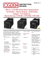
48mm, 1/16 DIN Solid State Temperature

Controller - Relay Output - Solid State

Output - For Heating - 

Model Series: ETR-901, ETR-902, ETR-905

ETR-901

ETR-902

ETR-905

All temperature controls in this series are made to fit
into panel cut-outs which measure 1

25

32

” (45mm)

square.  A minimum of 4” (102mm) in depth is required
for electrical clearances of rear terminal connections.
The following specifications are common to all models:

INPUT 

Thermocouple (T/C):

Type K, J.  Specified on 
Control Label.

RTD:

PT 100 ohm DIN (

.00385) or JIS (

.00392) Two or Three-Wire.

Cold Junction

Automatic        

Compensation:

Input Break Protection:

Built-in, upscale on open 
sensor and output off.

Input Impedance:

10M ohm.

Common Mode

Rejection (CMR):

CMRR 120 dB, Min.

Normal Mode

Rejection (NMR):

NMRR 60 dB, Min. (60Hz)

CONTROL OUTPUT

Relay–Heating:

SPDT relay, 3 amps     
maximum resistive load at 
120V/240VAC, 24VDC.

Optional: 3-32VDC:

For control of solid state 
relay.

CONTROL MODES

On-Off:

Hysteresis: 5.0% of scale 
symmetrically above and 
below the set point.

Proportional:

Proportional Band fixed at 
5% of scale.  Standard 
relay cycle time, 20       
seconds.  1 second for SSR
controls.On ETR-905,  
manual reset is 4% of 
scale, externally adjustable.

INDICATION

Output:

“Red” LED, heater on.

“Green” LED, heater off.

SET POINT

Resolution:

ETR-901, 902: 0.2% of 

SPAN.

ETR-905: least significant 

digit.

Accuracy:

ETR-901, 902: 0.2% of 

SPAN.

ETR-905: least significant 

digit.

Summary of Contents for ETR-901

Page 1: ...nsation Input Break Protection Built in upscale on open sensor and output off Input Impedance 10M ohm Common Mode Rejection CMR CMRR 120 dB Min Normal Mode Rejection NMR NMRR 60 dB Min 60Hz CONTROL OUTPUT Relay Heating SPDT relay 3 amps maximum resistive load at 120V 240VAC 24VDC Optional 3 32VDC For control of solid state relay CONTROL MODES On Off Hysteresis 5 0 of scale symmetrically above and ...

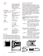
Page 2: ... Solid state relays can be single or three phase Following Diagrams for ETR 905 Model Diagram 3 For 90 264VAC operation and relay output An external magnetic contactor must be used if the heater load exceeds 3 amps Diagram 4 For 90 264VAC operation and 3 32VDC output For use with a solid state relay for heater control Solid state relays can be single or three phase NOTE The use of motor starters i...

Page 3: ...s All wiring must conform to appropriate standards of good practice and local and national codes and regulations Wiring must be suitable for voltage current and temperature ratings of the system Both solderless terminals or stripped leads as specified below can be used for power leads Only stripped leads should be used for thermocouple connections to prevent compensation and resistance errors Take...

Page 4: ... If more than 3A C N O N C 1 2 3 4 5 6 7 8 9 10 Red T C B B A 3 Wire RTD o o o o 120VAC 5A Fuse Hot 1 2 3 4 Solid State Relay o o Heater Power Heater Fuse Heater s 1 2 3 4 5 6 7 8 9 10 Red T C B B A 3 Wire RTD o o o o 90 260VAC 5A Fuse Hot Heater If less than 3A Contactor Coil If more than 3A C N O N C 1 2 3 4 5 6 7 8 9 10 Red T C B B A 3 Wire RTD o o o o 90 260VAC 5A Fuse Hot 1 2 3 4 Solid State ...

Reviews: